The purpose of this section is to collate and summarize the current state of knowledge and practice for removal of PFAS from water by sorption-based technologies and provide a resource to assist regulators, consultants, and industry practitioners as they navigate the decision-making process. Topics addressed in this document include treatment objectives, characteristics of commonly treated waters, potential site-specific considerations, operation and testing of fixed-bed and fractionation-based treatment technologies, resources for decision-making, and outstanding challenges for treatment implementation.
ITRC already provides resources to help with issues related to treatment of PFAS in water in the PFAS-1 Guidance Document. Section 12.2 includes a useful overview of the technologies discussed here (specifically, Section 12.2.1 and Section 12.2.3), as well as several other effective PFAS treatment technologies that are not sorption-based, such as membrane processes. Readers are advised to familiarize themselves with the summaries and concepts in Section 12 to take maximum advantage of the information presented here. That said, exhaustive knowledge of the earlier text is not necessary for understanding this new Section 18, and relevant sections will be referenced or summarized as needed. Readers should note that Section 12.2.1 is called “Sorption Technologies” and Section 12.2.3 is titled “Foam Fractionation,” but both fixed-bed adsorption by adsorbent media and adsorption to bubbles are considered “sorption-based” technologies in this Section. Readers specifically interested in point of use (POU) treatment or point of entry (POE) treatment (also referred to as POET) systems for treating drinking water, which are not specifically discussed in this new section, are advised to consult Section 12.1.4.1.
| Section Number | Topic |
|---|---|
| 18.1 | Introduction |
| 18.2 | Treatment Objectives and Considerations |
| 18.3 | Fixed-Bed Adsorbers |
| 18.4 | Foam Fractionation |
| 18.5 | Resources for Decision-Making |
| 18.6 | Barriers, Challenges, and Outlook |
18.1 Introduction
Removal of per- and polyfluoroalkyl substances (PFAS) from water has become an important concern for water utilities; landfill operators; industry professionals; and state, local, and tribal decision makers. One option for removal of PFAS from water is sorption-based technologies, which remove contaminants from the dissolved phase by adsorption to surfaces or absorption into bulk phases. Examples of sorption-based technologies include granular activated carbon (GAC), ion exchange (IX) resins, and foam fractionation. They have long-standing applications in water treatment and are recognized for their proven efficiency in removing PFAS. These technologies are frequently regarded as effective solutions due to their ability to target and remove a wide range of PFAS, especially longer chain PFAS (Murray et al. 2023; Tajdini et al. 2025), leveraging mechanisms that optimize contaminant capture and separation. Because of these characteristics, sorption-based technologies have planned or current deployment for PFAS treatment in more than half of US states (ECOS 2025). However, selecting the best treatment method or system configuration for removal of PFAS from water can be a daunting task, and PFAS-specific information on the topic is currently scattered across a variety of sources.
This section focuses on PFAS-specific concepts and practical considerations. It is not a nuts-and-bolts operational manual for water treatment systems, nor is it an exhaustive resource on the underlying physical principles of adsorption and absorption. Readers interested in gaining deeper or broader knowledge than can be provided here are advised to consult general texts on IX resins (Harland 1994; Helfferich 1995; Slater 2013; Zagorodni 2006), GAC (Worch 2012), foam fractionation (Lemlich 2012; Stevenson and Li 2014), and water treatment (Crittenden et al. 2012; Spellman 2008) as appropriate.
Only adsorptive technologies considered “field-implemented” by the ITRC (defined in Section 12.1) as of September 2025 will be discussed in this document. Although novel media technology such as surface-modified clays, cyclodextrins, and many others may have demonstrated PFAS removal under pilot or bench-scale conditions, they have not yet (September 2025) demonstrated maturity in full-scale treatment systems. Accordingly, it is not possible to provide specialized information on testing and evaluation for these technologies in practice. However, the testing methodologies described in this document are still expected to provide a useful foundation for testing and evaluation of these novel sorbents as they become more technologically mature. Where applicable, some new or emerging technologies for regeneration of GAC and IX resins or destruction of treatment residuals are briefly discussed. Removal of PFAS from water in ex situ treatment systems by addition of powdered activated carbon (PAC) is not cost-effective except in some cases where modest PFAS removal (50% or less) is needed and a method for dealing with resulting sludge is available (Ahrens et al. 2025). Therefore, testing and evaluation of PAC are not examined here.
Ex situ treatment applications such as wastewater (industrial or municipal) treatment, treatment of extracted groundwater, and drinking water treatment, which are the focus of this document, have significant overlaps in site assessment, testing, and evaluation processes. In situ remediation methods, such as injection of colloidal activated carbon or other sorbents, differ significantly from ex situ methods in all these aspects and fall beyond the scope of this document.
18.1.1 Additional Resources
This section extends but is also distinct from content provided in the previously published PFAS-1 Document (https://pfas-1.itrcweb.org). Therefore, prior to continuing in this section, readers may find it useful to review and familiarize themselves with the following sections and external data tables:
- Section 8: Basis of Regulations – PFAS – Per- and Polyfluoroalkyl Substances
- Section 8: PFAS Regulatory Programs Summary Excel File
- PFAS Environmental Media Values Table Excel File
- Section 10: Site Characterization
- Section 12.1.1: Factors Affecting Technology Selection
- Section 12.1.4: Considerations for Specific Environmental Media
ITRC offers other resources covering in situ treatment technologies, including Section 12.2.4 and Section 15.2.3 and relevant slides in the ITRC PFAS Beyond the Basics: PFAS Treatment Technologies Training.
Some commonly asked questions about PFAS treatment methods are mapped to their respective sections in the section in Figure 18-1.
Information about Strategic Environmental Research and Development Program (SERDP) and Environmental Security Technology Certification Program (ESTCP) projects for sorption-based technologies can be found at https://serdp-estcp.mil/.
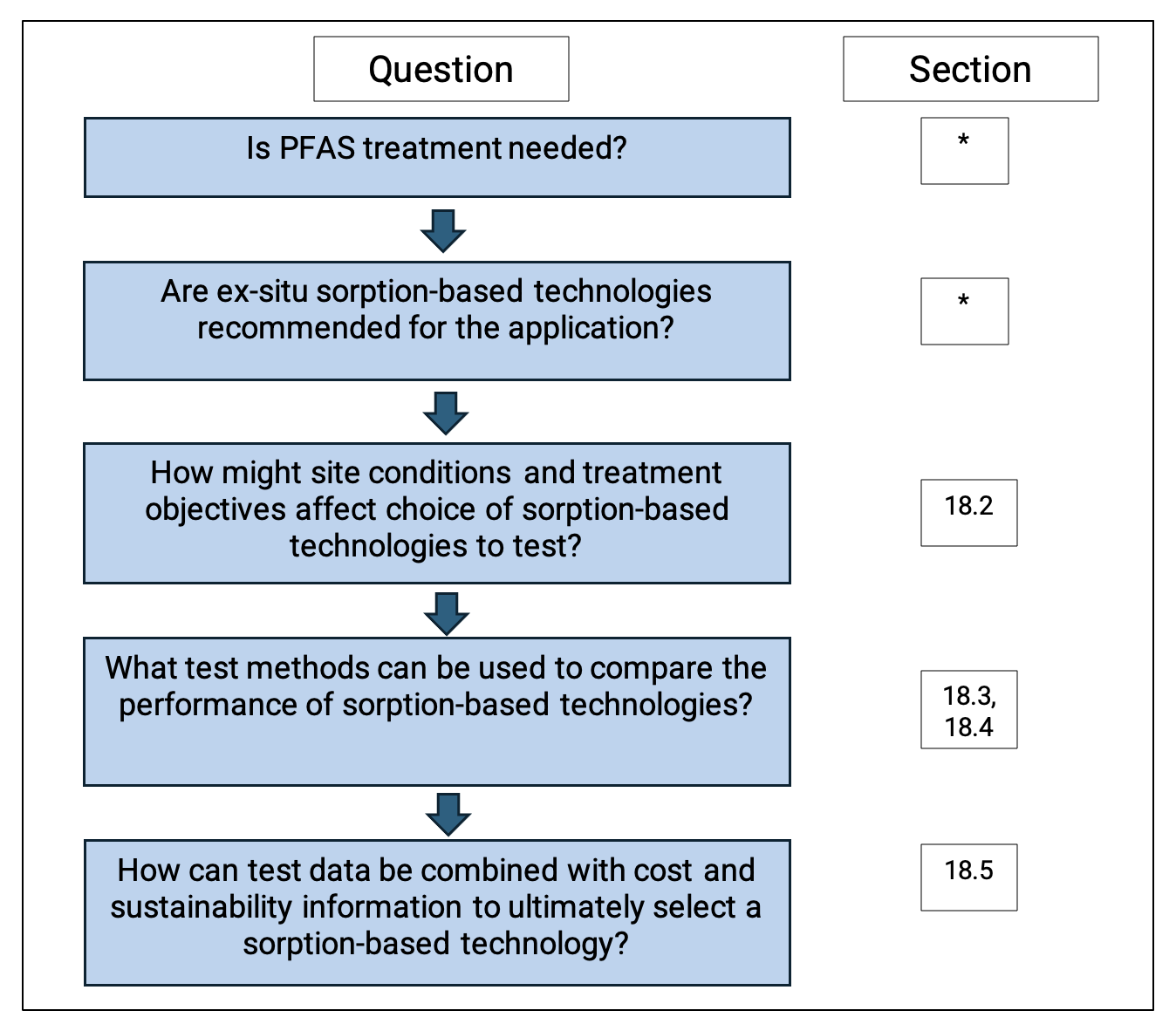
Figure 18-1. Diagram mapping document sections to pertinent questions for planning, testing, and evaluating sorption-based treatment options for PFAS in water. An (*) denotes questions answered before consulting this document using guidance from other resources, such as Section 8 (Basis of Regulations) and Section 12.1.1 (Factors Influencing Technology Selection).
18.2 Treatment Objectives and Considerations
18.2.1 Introduction
Location selection and sizing of sorption-based PFAS treatment facilities require a comprehensive evaluation of various factors, including PFAS treatment objectives, characterization of waters commonly treated and their influence in treatment process selection, and flow quantification. This section discusses these and other operational considerations. By thoroughly understanding these considerations, informed decisions can be made that balance efficiency, cost, and space constraints to develop an optimal PFAS treatment strategy.
18.2.2 Objectives
It is important to first recognize that the objective of sorption-based PFAS treatment is to remove PFAS from the water or liquid waste stream such that the treated water is made suitable for some consumptive use or discharge. This is different from the objectives specific to remediation of a contamination site, but the use of such treatment may contribute to site remediation objectives. For the purposes of this guidance, all applications of treatment are ex situ. Treatment using GAC and IX resins achieves this objective by separating and concentrating PFAS onto the sorption media, while foam fractionation achieves this objective by separating and concentrating PFAS into a separate solution of reduced volume. Enhancing the concentration of separated PFAS allows it to be more efficiently and economically destroyed or properly disposed. Detailed discussion regarding the use of additional treatment for destruction of PFAS or technology for the containment/disposal of the separated PFAS is outside the scope of this guidance, but some factors regarding destruction and disposal are mentioned. Additional information on these destruction technologies is available in the following sections:
- Section 12.4 Incineration
- Section 12.6 Limited Application and Developing Liquids Treatment Technologies
- Section 12.6.3 Redox Manipulation
- Section 12.6.5 Alkaline Hydrothermal Reaction
The amount of removal needed will depend upon the concentration of PFAS in the source water or liquid waste stream and the intended end use or point of discharge and regulatory requirements. PFAS may be regulated individually, in combination with other PFAS or precursors, or both. Users can refer to the PFAS Environmental Media Values Table, and the Environmental Council of the States (ECOS) Compendium of State PFAS Actions, (ECOS 2025) for additional information regarding state- or country-specific regulatory information.
18.2.2.1 Consumptive Use Objectives
PFAS treatment of groundwaters or surface waters for consumption may include nonpotable uses but is more commonly associated with the production of drinking water. Treatment objectives to produce drinking water are related to public health, limiting the risk of potential health effects by limiting the concentrations of PFAS regulated in drinking water and thus limiting exposure to those contaminants. Concentrations may be established through primary standards, treatment techniques, goals, advisory levels, etc. There may be differences between concentrations associated with a regulatory goal and the minimum level of treatment established by a standard. These could be due to economic and technological limitations (for example, limits in the ability to practically quantitate the concentration of a particular PFAS). Despite such limitations, a drinking water supplier and its customers may establish treatment objectives that provide a level of service that goes beyond minimum regulatory requirements (for example, to produce water with no detectable levels of regulated PFAS, or to limit the concentration of certain unregulated PFAS). Achievement of PFAS treatment objectives for drinking water utilities is typically determined at the entry point into the distribution system, rather than at individual customer taps. Where PFAS treatment is provided for an individual household with a privately owned well, achievement of objectives may be determined either in the household after point of entry treatment for all uses, or at specific points of drinking water use.
18.2.2.2 Discharge Objectives
The objective of sorption-based PFAS treatment for the discharge of generated liquid waste streams is to reduce the concentration or mass loading, or both of regulated PFAS in the discharge to restore and maintain the chemical, physical, and biological integrity of the receiving water for the protection of public health, environmental, and designated uses. Wastewaters where sorption-based PFAS treatment may be used to meet discharge objectives may include but are not limited to municipal sewage, industrial process wastewaters, landfill leachates, contaminated groundwater, contaminated dewatering water, membrane reject concentrate, containment waters, and managed construction site water. Sorption-based PFAS treatment may also be applied to industrial or municipal stormwater to achieve discharge objectives. Discharge objective criteria may be associated with:
- Regulated PFAS concentration or loading based on achieving certain water quality
- Regulated PFAS concentration or removal efficiency based on the treatment technology being applied
- Regulated PFAS concentration or loading established by a local publicly owned treatment works (POTW) based on contaminant loading to the POTW and ability to maintain its own discharge objectives
- Industry-specific guidelines
- Highest attainable conditions under standard variances or Pollutant Minimization Program goals where concentration reductions can occur over time with interim criteria
- Corporate or governmental environmental stewardship program goals
Objectives for discharges to groundwater may be associated with a specific use(s) of that groundwater for protection of human or ecological receptors, such as use as a source of drinking water by individual household private wells or public water utilities’ wells. Discharge of some wastewaters to groundwater may be prohibited, depending on the nature of the liquid waste stream being generated, either categorically or in accordance with antidegradation requirements.
As listed above, discharges to a POTW may be subject to limitation of PFAS concentration and mass loading to the wastewater treatment plant to prevent pass-through of untreated PFAS and interference with the operation or performance of the treatment plant. This may include interference with the ability to land-apply biosolids or to provide other beneficial use. Because these limitations are established based on the needs of the individual wastewater treatment plant, they can vary widely, and individual POTWs should be consulted to verify requirements. Similarly, co-contaminants within the waste streams or additives used as part of the PFAS treatment process could also be subject to local limitation and could affect the efficiency of PFAS removal.
During the treatment method selection, the practitioner may evaluate more than one of the discharge options listed above where PFAS treatment objective criteria differ. Valuable insight on recommended practices for discharge of PFAS-contaminated treated water and liquid waste streams under the National Pollutant Discharge Elimination System (NPDES) program is provided in a December 5, 2022, US Environmental Protection Agency (USEPA) memorandum on “Addressing PFAS Discharges in NPDES Permits and Through the Pretreatment Program and Monitoring Programs” (USEPA 2022).
The USEPA has since published (draft as of December 2024) national recommended human health ambient water quality criteria for perfluorooctanoic acid (PFOA) (USEPA 2024), perfluorooctane sulfonate (PFOS) (USEPA 2024), and perfluorobutane sulfonate (PFBS) (USEPA 2024). The criteria provide recommendations as part of the development and adoption of water quality standards, but as stated in the associated USEPA Technical Fact Sheet, “National recommended human health ambient water quality criteria are not regulations, nor do they impose legally binding requirements.” The USEPA has also published Final Recommended Aquatic Life Criteria and Benchmarks for Select PFAS (USEPA 2024; USEPA 2024; USEPA 2024).
In some circumstances where no existing regulations currently apply, but a reduction in PFAS is desired, PFAS treatment objectives may be determined by the responsible party.
18.2.2.3 Additional Objective Information
In addition to concentration, mass load, and removal efficiency components of PFAS treatment objectives are the components related to the location used to determine whether a PFAS treatment objective has been met, the treatment objective assessment frequency, and any calculation associated with determining whether the PFAS treatment objective has been met. For PFAS treatment objectives associated with consumptive uses, such as drinking water, the location for determining whether a treatment objective has been met may be an entry point to where water is distributed, a specific point of entry, or a specific point or points of end use. Locations for determining whether PFAS treatment objectives associated with discharges have been met may include the point of effluent from the treatment system itself, the point of discharge (to a water body, a POTW, or groundwater), or monitoring wells. Reporting of monitoring at additional locations, such as influent or raw water, between stages of adsorptive media vessels or within media beds, may not be used to determine whether a PFAS objective has been met, but may inform the state of operational performance to help ensure a PFAS treatment objective will continue to be met. The assessment frequency for determining whether a PFAS treatment objective has been met may vary depending on the type of discharge or consumptive use or vary from location to location within the same treatment system. Assessment frequencies for PFAS treatment objectives can range from daily maxima to monthly averages to annual or running annual averages. Determinations may also be based on individual batch discharges. The PFAS treatment objective assessment frequency can factor in treatment design, redundancy, operation, and maintenance provisions.
It is also important to understand how qualified analytical results may be used in determining whether a PFAS treatment objective has been met. This includes the occurrence of estimated concentrations between method detection limits and a practical quantitation limit, or laboratory limit of quantitation, as well as when matrix interference causes the limit of quantitation to increase the concentration associated with reporting detections.
In some circumstances PFAS treatment objectives may be prescribed based on minimum operational conditions (WI DNR 2022). These may include minimum amounts of empty bed contact time (EBCT), maximum treated bed volumes between change-out of fixed-bed sorptive media, changing of lead/lag unit positions, or reporting of these tank rotation or media change-out conditions (MI EGLE 2024).
Although not directly tied to PFAS treatment objectives for consumption or discharge of waters, additional PFAS objectives may be associated with releases of air to the indoor environment or atmosphere that potentially contain PFAS associated with sorption-based PFAS treatment, or volatile co-contaminants. Pressure vessels used for fixed-bed adsorptive media include air vacuum/air release valves to allow for the flow of air in and out of the vessel. These air release valves are known to release small amounts of water as they close. Vapor-phase emissions from these vent valves in fixed-bed sorptive media vessels are assumed to be de minimis. Foam fractionation systems input air or gases into the treatment system that must also exit from the system. These releases of air or gas may include vapors or aerosols containing PFAS. There is ongoing research into the magnitude of these potential releases and several studies funded by the Environmental Security Technology Certification Program (ESTCP) are collecting samples to quantify PFAS in air emissions from foam fractionation (for example, Sorenson 2023; Sorenson 2023). The use of additional controls or air monitoring may be considered to meet objectives associated with these discharges of air.
It is important to determine PFAS treatment objectives at all levels of authority—federal, tribal, state/territory, and local—as one authority may have established objectives that are more restrictive than another. PFAS treatment objectives are expected to evolve as additional knowledge is accrued regarding the human health effects and toxicology associated with these contaminants, and as analytical method limits of quantitation are refined. By staying informed of proposed and future changes that could add or modify PFAS treatment objectives, the selected treatment can be evaluated in its ability to meet such objectives or configured to allow for expanded PFAS treatment if needed in the future. These changes could include:
- Changes to regulated PFAS
- Changes to treatment objective concentrations or mass loading
- Changes to treatment removal efficiency objectives
- Changes to Pollutant Minimization Program goals or standard variance highest attainable condition target objectives
18.2.3 Characterization and Pretreatment Needs
The water to be treated must be adequately characterized to evaluate available treatment technologies. This includes characterizing the PFAS content of the water to be treated, the types of PFAS present and their respective concentrations, the concentration of co-occurring constituents, and other parameters. Both regulated and unregulated PFAS should be considered, including precursors. This information can be used to help understand competition for sorptive sites and to determine sorbent media loading capacity before saturation.
For industrial facilities, municipal wastewater treatment plants, and stormwater systems, making efforts to reduce or eliminate identified sources of PFAS to the extent practicable prior to determining the need for treatment can provide benefits such as reducing PFAS mass loading or the flow requiring treatment. These reductions can be achieved through industrial pretreatment programs, reducing or eliminating exposure to stormwater, industrial process and material changes, etc., and are normally more cost-effective in addressing PFAS than treatment of less concentrated and greater flow wastewaters and stormwaters at downstream points.
PFAS concentrations typically encountered in surface- and groundwaters across many different release sites, such as aqueous film-forming foam (AFFF) release sites, industrial facilities, and landfills, range from 0.1 to 10,000 parts per trillion (ppt) (Section 6.3 and Section 6.4). PFAS concentrations in industrial wastewater discharges (MI EGLE 2020; MI EGLE 2020) and landfill leachates (Sabba et al. 2025), however, can be substantially higher—up to the low parts per million range. These potentially elevated concentrations can simply be due to the nature of the waste stream, such as in landfill leachate, or can be the result of a concentration step, such as reverse osmosis. Although all these sources have been treated with sorption-based technologies, highly concentrated sources require further evaluation of pretreatment needs, co-constituents, operation and maintenance (O&M) costs (for example, media change-out frequency).
Waters with highly complex background chemistry, such as landfill leachates, tend to have rapid PFAS breakthrough in sorptive media, as they often exhibit high total organic carbon (TOC, ~ 560 mg/L) and total dissolved solids (TDS) concentrations (~ 60,000 mg/L) (Murray et al. 2023; Malovanyy et al. 2023). These types of waters may be treated with minimal pretreatment with foam fractionation, depending on treatment objectives and type and concentration of co-constituents. Foam fractionation removal of PFAS is positively impacted by TDS, while TDS may deteriorate GAC and IX resin performance. Both GAC and IX resins may need pretreatment for organic carbon and metals removals while foam fractionation largely does not (Buckley et al. 2022).
For groundwaters and drinking waters with PFAS influent in the low-level ppt range, sorptive media are often the most cost-effective treatment option because the media will have a long lifetime, minimizing O&M. For media beds designed with typical EBCTs (see Section 18.3.1.1 for IX and GAC), generally IX resins, including regenerable resins, provide a longer run time or total volume throughput to breakthrough for sulfonate PFAS compared to GAC (Kassar and Boyer 2023; Liu et al. 2022). More discussion about the relative efficacy of GAC and IX resins can be found in Section 18.3.1.6. The more frequently treatment media need to be replaced, the more economically favorable a reusable media or foam fractionation approach may become (Kempisty et al. 2024). However, other factors, including removal efficiency, cost of maintenance and repair, and efficiency should be considered.
Solution characterization should also consider physical characteristics and the presence of co-contaminants—those that may interfere with treatment and those that are also regulated for simultaneous compliance considerations. Co-occurring organics, inorganics, and ions have all been demonstrated to affect PFAS treatment technologies and should be considered during the characterization of waters to be treated as different types of media might be needed (Zeidabadi, Esfahani, and Mohseni 2023). The presence of these water quality constituents may require pretreatment technologies to maintain effective PFAS treatment based on their concentration and the selected PFAS treatment method(s). Most adsorbents aside from gases are negatively impacted by organic compounds (for example, natural organic matter (NOM) in groundwater and surface water, as well as effluent organic matter in wastewater). Therefore, characterizing the organic matter by analyzing TOC or dissolved organic carbon (DOC) concentrations, or both is of critical importance. Total and dissolved fractions of iron and manganese should be analyzed due to their potential to foul media. Dissolved oxygen and oxidation/reduction potential also should be analyzed to determine natural or contaminant-induced redox conditions; microbial activity may impact treatment system fouling, especially for surface water and stormwater runoff treatment, and must be evaluated. The use of the Langelier Saturation Index (LSI) can be helpful in assessing the likelihood for calcium carbonate scale formation, which can also negatively impact adsorption media. Calculation of the LSI requires the following parameters: TDS concentration, pH, alkalinity, calcium concentration, and temperature. Depending on the source of the stream requiring treatment, characterization of volatile organic compounds (VOCs) and the oil and grease concentration may be important as well. Characterizing the nitrate, sulfate, and chloride concentrations is also important for applications using anion exchange IX resins.
Seasonal conditions can impact treatment. For example, nitrate from agricultural runoff and chloride salts from road de-icing can potentially interfere with the performance of IX resins treating ground or surface waters. Similarly, pH and organic matter, both of which can influence effectiveness of adsorption for several technologies, may also vary with seasonal conditions. Water sources impacted by industrial sources may experience high variability in PFAS concentrations, especially if operation of the industrial processes is seasonal or intermittent. Storm events and differences between dry weather and wet weather, including first-flush water quality conditions, should be evaluated to determine impacts to sorption-based treatment systems and pretreatment needs. This includes mobilized silt, sediment, turbid waters, and debris that can cause fouling.
Drinking water utilities may use multiple source waters of varying quantity and quality. If centralized treatment is being planned, all sources should be characterized to understand worst-case conditions and variation of co-contaminants.
Various water sources have differing water chemistries, which create differing alleviations or stressors on adsorption-based solutions. For example, landfill leachate and wastewater typically contain high TOC, which may take up sorption spaces on some technologies and affect downstream destruction. Similar membrane concentrates and IX regeneration brines may have high salinity, which may affect sorption as well as downstream destruction. Table 18-1 includes examples of co-contaminants and other water quality parameters that may interfere with sorption-based treatment technologies based on information in Section 18.3 and Section 18.4. Interference by co-contaminants depends on composition and concentration. For instance, presence of VOCs does not necessarily mean that PFAS removal by GAC will be heavily degraded (Haupert et al. 2023). Also, IX resins with different morphologies and chemistries have differing resistance to attack by oxidants, with macroporous resins being more rugged than gel-type resins. More details on interference by co-contaminants can be found in Section 18.3 and Section 18.4.
Table 18-1. Interference of water quality parameters with sorption-based PFAS treatments
| GAC | IX Resins | Foam Fractionation | |
|---|---|---|---|
| Suspended Solids | X | X | X |
| TOC | X | X | |
| Total Dissolved Solids (TDS) | X | X | |
| DOC | X | X | |
| Fe | X | X | X (if oxidized) |
| Mn | X | X | X (if oxidized) |
| VOC | X | X | |
| Oils, Fats, Greases | X | X | X |
| Bacteria/Algae | X | X | |
| Disinfectants/Oxidants | X | X | |
| Nitrate | X | ||
| Sulfate | X | ||
| Chlorides | X | ||
| Phosphate | X | ||
| Alkalinity | X | X | |
| Hardness | X | X | X |
| pH | X | X | |
| Total and Dissolved Silica | X | X | X |
The need for pretreatment prior to PFAS treatment can be substantially different from treatment of other contaminants. Pretreatment needs are directly related to the specific water or liquid waste stream and its geochemical properties. Assessing pretreatment needs and options is an important part of bench and pilot testing. Co-contaminants and other water constituents, such as total organic matter, solids, metals (for example, iron and manganese Speth 2022), and turbidity, can adversely affect the removal efficiency (decreased), operational life (decreased lifespan, increased media replacement frequency), and effort (for example, staffed operational hours, complexity and difficulty of maintenance tasks).
18.2.3.1 Types of Pretreatment
The type and extent of pretreatment can vary based on the PFAS treatment technology(ies) used. GAC, IX resins, and foam fractionation all generally require water and liquid waste stream co-contaminants to be removed and geochemical conditions improved to operate effectively. Table 18-2 presents information about pretreatment methods summarized from information in Section 18.3 and Section 18.4 and cited literature therein. Operational and maintenance practices such as backwashing GAC may also be beneficial in managing adverse effects of water quality parameters on PFAS treatment.
Table 18-2. Pretreatment methods, water quality parameters pretreated.
| Pretreatment | Suspended Solids Removal (for example, bag, cartridge, sand filters) | Iron and Manganese Removal (for example, greensand, aeration, oxidation) | Chemical Addition (anti-scaling agents, pH control, sodium bisulfite) | Ion Exchange (for example, water softening, demineralization, organic scavenger resins) | Membrane Processes (for example, nanofiltration) | Oil-Water Separation (for example, oil-water separators, organoclay) | Air Stripping | Settling/Clarification Tank (with or without coagulant or polymer addition) | GAC (sacrificial) | Disinfection (for example, UV, chlorine, ozone, biocides) |
|---|---|---|---|---|---|---|---|---|---|---|
| Water Quality Parameter Addressed by Pretreatment | ||||||||||
| Suspended Solids | X | X | X | X | ||||||
| TOC | X | X | X | X | ||||||
| TDS | X | X | X | X | ||||||
| DOC | X | X | X | X | X | X | ||||
| Fe | X | X | X | X | X | X | X¹ | |||
| Mn | X | X | X | X | X | X | X¹ | |||
| VOC | X | X | X¹ | |||||||
| Oils, Greases, Fats | X | X¹ | ||||||||
| Nitrate | X | X | ||||||||
| Sulfate | X | X | ||||||||
| Chloride | X | X | ||||||||
| Scaling (for example, carbonate, hardness) | X | X | X | |||||||
| Phosphate | X | X | X | X | X | |||||
| Alkalinity | X | X | X | |||||||
| pH | X | |||||||||
| Total and dissolved silica | X | X | ||||||||
| Bacteria/Algae | X | X | ||||||||
| Disinfectants/Oxidants | X | X | ||||||||
1 Disinfection techniques using oxidants may also treat the indicated water quality parameters.
Further, changes of organic matter characteristics (for example, aromaticity, molecular weight) through emerging pretreatment strategies such as ozonation (O3) and biologically active filtration (BAF) have been shown to substantially improve PFAS removal in subsequent sorption-based treatment technologies (Tajdini et al. 2023). Vatankhah et al. (2022) demonstrated that low-dose ozonation transforms high molecular weight organic compounds into smaller, more bioavailable assimilable organic carbon, which reduces pore blockage and decreases site competition with PFAS molecules, ultimately improving PFAS removal during subsequent sorption. Dai et al. (2019) demonstrated a pilot-scale ozonated air fractionation and combined UV/ozone treatment for PFAS. BAF is another pretreatment strategy used for biodegradation or biotransformation of organic matter that ultimately leads to improved PFAS removal in the subsequent sorption step. Both ozonation and BAF, whether applied individually or in combination as pretreatment, enhance PFAS sorption in the subsequent treatment stage, with the combined configuration demonstrating the greatest improvement in performance (Vatankhah et al., 2022). However, it is also important to recognize that oxidation conditions can alter transformation product distribution and the range of intermediates and PFAS produced. Unintended generation of nontargeted intermediates or ultrashort-chain PFAS (ultrashort PFAS) may also occur during oxidation. For example, nontargeted products can occur during oxidation of PFAS with ether functional groups (Ateia et al. 2023). Our understanding of PFAS oxidation and biotransformation processes is limited and use of these pretreatment systems should be thoroughly evaluated.
18.2.4 System Size
Estimates should be made regarding the rate of flow to be treated and the variability of that flow. Both present and future flow parameters should be considered over the expected design life of the treatment system. All of the sorption-based treatment systems presented in this guidance can be expanded with additional units to accommodate future flows using parallel treatment trains if needed, but this requires adequate planning. Examples of planning concepts to be considered are provided in this section.
Drinking water systems should be capable of meeting peak hour or instantaneous water demands. Existing or additional treated water storage volumes can be used to reduce the treatment flow capacity needed. The cost of additional treated water storage can be compared to the cost of treatment capacity. If treatment is centralized for multiple sources of water, flow rates and water quality associated with different source combinations should be considered when evaluating treatment capacity needs.
Municipal wastewater systems may need to consider diurnal flow conditions, the impact of inflow and infiltration, and combined sewer flow, along with flow and water quality from separately received materials, such as septage, hauled liquid wastes, and leachates, when evaluating treatment flow capacity needs. Industrial wastewater systems must consider what process flows will require treatment and how often those flows are generated. Landfills must consider the amount and quality of leachate generated from existing cells and the amount of leachate that will be generated from future cells. Landfills should also evaluate other flows for PFAS treatment, such as underdrain systems. Wastewater equalization storage capacity can be used to reduce the treatment flow capacity needed.
Scientists can measure dry weather flow conditions of stormwater systems and evaluate the volume of stormwater generated within PFAS-impacted catchment areas during various targeted storm events to select the desired treatment flow capacity and equalization storage capacity.
When treatment system effluents are beneficially reused (for example, on-site irrigation or dust control), the need for storage or alternative discharge/disposal methods can also affect system size needs. Such conditions can occur when on-site soils are saturated (for example, from storm events). The case study provided in Section 15.2.4.1 provides an example of a foam fractionation treatment system with beneficial reuse of the treated water for on-site irrigation.
18.2.4.1 Footprint and Spacing Requirements
In addition to media selection, the size of PFAS treatment facilities is influenced by several factors, which determine the capacity and scalability of the treatment system. Before full-scale implementation, rapid small-scale column testing (RSSCT) and piloting are often important to validate the effectiveness of fixed-bed sorption media. The value of RSSCT and pilot testing depends on site-specific conditions such as PFAS type and concentration, the presence of adverse water quality parameters, treatment objectives, and permit requirements. For example, an RSSCT for a water stream with minimal potential fouling conditions and low PFAS concentrations may be of limited value compared to a water stream with significant potential fouling conditions, high PFAS concentrations, or both.
RSSCT involves using small-scale columns to simulate the performance of the treatment media under real-world conditions. This testing helps determine the optimal design parameters, such as appropriate contact time and the estimated number of bed volumes that can be treated before media replacement or regeneration is needed for each media being evaluated. Pilot studies involve deploying a smaller version of the treatment system to gather data on its performance, operational challenges, and efficiency. This step is crucial for refining the design and ensuring reliability before scaling up.
Residence time is the duration that a water or liquid waste stream must be processed within a treatment unit. For GAC, IX, and some pretreatment technologies (for example, sand filtration), this is commonly referred to as empty bed contact time (EBCT). For foam fractionation and some pretreatment technologies (for example, solids coagulation, flocculation, and settling), this may be referred to as hydraulic residence time (HRT). PFAS residence times are generally highest in foam fractionation systems, followed by GAC, followed by regenerable IX resin, followed by single-use IX resin. Typical HRTs for foam fractionation range from 25 to 60 minutes (We et al. 2024). Typical ranges of EBCTs for GAC and IX are provided in Section 18.3.1.1. The specific residence time can vary between equipment design, media type, operating conditions, and the quality of the water or liquid waste stream treated. If there is limited space for PFAS treatment available, the sizing of equipment for any given flow rate and the corresponding treatment footprint is largely related to HRT or EBCT. Any required pretreatment or regeneration equipment would also add to the system footprint. The amount of fractional removal to meet PFAS treatment objectives may influence the treatment technology selection as well as the treatment system design. A system needing to achieve a 99.9% reduction in PFAS may need a more robust treatment design than one needing only a 50% reduction to meet the same concentration treatment objective. This could include more EBCT, longer batch times, or additional stages of treatment, or some combination of these.
As a hypothetical example, a containerized foam fractionation system may be able to treat 1,000 gallons of PFAS-contaminated groundwater over a 30-minute batch process in each of two primary fractionation tanks sized 6 feet in diameter with a water column 5 feet in height. Under this example, by alternating tank filling and processing, the system would be able to process 96,000 gallons operating 24 hours per day. However, if a municipal wastewater treatment plant that processes a higher flow of 1,000,000 gallons per day but with lower concentrations of PFAS needs a longer 60-minute batch processing time, the same containerized foam fractionation system would be able to treat only 48,000 gallons operating 24 hours per day, and 21 of these foam fractionation units would be needed to achieve a capacity of 1,000,000 gallons per day.
Under a hypothetical example for GAC, using 20 minutes of EBCT, two 8-foot diameter pressure vessels in a lead-lag configuration with a bed depth of 7 feet would be capable of treating a flow of 263 gallons per minute or 378,800 gallons per day under 24-hour operation. A municipal wastewater treatment plant needing to process 1,000,000 gallons per day would need to install at least three parallel treatment trains of these two-tank lead-lag systems. The pressure vessels alone would require approximately 400 square feet of spacing, along with more than 12 feet of ceiling height. This could be compared to a single-use IX system using 4 minutes of EBCT and two 3-foot-diameter pressure vessels in a lead-lag configuration with a bed depth of 5 feet, which would be capable of treating a flow of 132 gallons per minute or 190,250 gallons per day under 24-hour operation. The same municipal wastewater treatment plant needing to process 1,000, 000 gallons per day would need to install at least six parallel treatment trains of these two-tank lead-lag systems. However, the pressure vessel spacing requirements would be reduced to 108 square feet with a ceiling height of 10 feet.
18.2.5 Additional Site-Specific and Operational Considerations
Although PFAS treatment equipment and systems have many similarities to those used for treatment of other contaminants (for example, petroleum and chlorinated hydrocarbons, solids, and metals), there are operational considerations that are specific to or similar but significantly more critical to PFAS treatment for water and liquid waste streams.
18.2.5.1 Installation At Sites or Facilities with Existing Treatment
Treatment of existing water and liquid waste streams that were not previously treated for PFAS (for example, drinking water treatment plants, landfill leachates, industrial wastewater discharges, and contaminated groundwater treatment systems) is a growing need. Technologies used in existing treatment systems for conventional and other non-PFAS contaminants are typically unable or insufficient to effectively treat PFAS. For example, a treatment system for an industrial wastewater discharge may include GAC, but the type of GAC and system design (for example, contact time, flow rate) currently in use are insufficient to remove the PFAS loading present. Some water and liquid waste streams may not have any treatment, such as some groundwater wells used to provide drinking water. These situations present challenges of incorporating PFAS treatment (and possibly pretreatment) within current space and utility constraints. Additionally, it may be necessary to implement immediate corrective actions while a longer term solution is developed.
Placement of sorption-based PFAS treatment for most existing municipal wastewater treatment plants and drinking water treatment plants will typically be as a tertiary process. For fixed-bed media systems, this reduces co-contaminant loading to the GAC or IX and helps limit the need for additional pretreatment. Foam fractionation systems may have more flexibility in their placement; however, placement as a tertiary process will limit the potential for generating odors. In municipal wastewater treatment plants, placement to treat a substream of plant flow, such as solids processing decant water recycle flow, may be considered depending on its PFAS load contribution. The placement of these sorption-based PFAS treatment systems in relation to disinfection processes must also be considered. The presence of chlorine or chloramines can cause degradation of anion resins. GAC will reduce or remove these disinfectants from the water. Similarly, the introduction of air or gases in foam fractionation can also reduce or remove disinfectant residuals. At the same time drinking water treatment plants and municipal wastewater treatment plants must maintain sufficient disinfectant contact time to meet their respective regulatory requirements. Non-PFAS co-contaminant simultaneous compliance treatment needs should also be evaluated. For example, because GAC can also be used to effectively reduce concentrations of disinfection byproducts, in a situation where the present value cost of a GAC system to address PFAS in drinking water is greater than other PFAS treatment technologies, the added benefit of disinfection byproduct removal may still make GAC treatment a preferable overall alternative.
Hydraulic evaluations should also be conducted at existing treatment systems to determine whether existing pumping equipment remains sufficient or requires modification, or if it should be used to meet the needs of the proposed PFAS treatment equipment to avoid the need for double pumping. GAC and IX media beds will create additional pressure head losses that must be overcome. The evaluation should consider the full range of pressure head loss increase over the fixed-bed media life cycle, including fouling potential. This type of planning may help avoid the need for premature media change-outs before full use of media sorption capacity can be achieved. The system must be able to maintain its rated treatment flow capacity.
18.2.5.2 Treatment Space Considerations
The following list of considerations should be evaluated when developing a treatment site layout:
- Sizes of treatment tanks, vessels, or containerized units
- Sizes of pretreatment equipment
- Space for pumps, piping, and other equipment
- Space for fixed-bed media storage, change-out, and delivery
- Space for chemical storage, feed systems, and delivery
- Space for control systems
- Sufficient space for operator access to repair and maintain equipment
- Equalization storage
- Treated water storage
- Backwash water storage
- Space for on-site monitoring and analytical equipment
- Space for mechanical, electrical, and plumbing equipment
- Space to allow for future treatment expansion or building addition
- Space for repair or replacement parts, particularly those with long lead times
- Heating and cooling needs, including freeze protection of exterior or unheated equipment
- Facilities for operator(s) (for example, restrooms, potable water, hot water)
- Space compliant with building, electrical, mechanical, and plumbing codes
18.2.5.3 Site Location Utilities
Selecting an optimal location for PFAS treatment facilities involves several logistic and regulatory factors. Adequate land availability is essential for the construction and operation of treatment facilities. Zoning regulations must be considered to ensure the site is suitable for industrial use and complies with local land-use policies. Locating the treatment facility close to the PFAS-contaminated water that will be treated minimizes the need for extensive piping and reduces potential to create or exacerbate contamination areas during water transportation. At the same time, the treatment system should be in an area that is easily accessible for maintenance, monitoring, and the delivery and removal of treatment materials.
Proximity to transportation infrastructure can help keep facility operations efficient. If access roads must be provided, ensure that they are sufficient for delivery vehicles with spacing provisions for delivery and pickup positions, and turnarounds. Determine whether seasonal weight restrictions on roads to and from the proposed treatment site may limit bulk delivery of consumables such as GAC, IX resin, or treatment chemicals to the site, or limit the off-site transport of spent media or foam concentrate for destruction or disposal.
Determine what source(s) of water are available at or near the proposed treatment site. The largest demands for water will generally be associated with any applicable fire protection needs, backwash operations for the specific media (Section 18.3), or safety equipment such as eyewashes or showers. If a source of backwash water is needed, it must be available at appropriate flow rates or stored in sufficient volumes for the duration of the backwash cycle. Consider whether the quality and quantity of treated effluent could be used for any of these water demands. Evaluate options for the disposal or treatment of backwash water. Although existing pretreatment processes such as coagulation/flocculation followed by clarification may be able to remove the solids loading from backwash recycled to the influent of the treatment system, some storage of the backwash may be necessary to limit the percentage of recycled backwash making up the influent flow to the treatment system. In some cases, it may be necessary to provide sufficient volumes of stored water on-site.
Determine the availability and capacity of electric and natural gas utilities and whether these resources are adequate to address the needs of the proposed treatment system. GAC and IX systems needs will depend largely on the total dynamic head loss that must be overcome by pumping systems. Head losses will depend on the media properties, vessel design (for example, media bed depth and underdrain design), EBCT requirements, and the number of stages used in the treatment process. Foam fractionation systems use several different pumping systems, including those used in the bubbling process, which make up a significant portion of the electrical capacity requirements. Pretreatment systems will also add to electrical demand considerations.
Any backup power requirements should be verified with the treatment system vendor(s) and any applicable regulatory authority. Some facilities are required to provide backup power for continuous operation. Some treatment equipment may need a limited supply of backup power to allow for a properly controlled shutdown of equipment, in accordance with the manufacturer/vendor requirements. If the facility has an existing source of backup power, it should be checked to determine whether it has enough remaining capacity to handle this additional load.
Security needs to prevent unauthorized access to treatment systems should be considered, including items such as fencing, video surveillance, intrusion alarms, and electronic fire walls. Higher security may be applied to certain areas of higher hazard. For example, some chemicals and equipment used in IX regeneration can be designated as hazardous classified locations where fire or explosion hazards exist. Spill containment provisions should be determined along with the need for containment of stormwater in areas where potential exposures exist at the treatment site. Consider whether these containment waters can be processed by the proposed PFAS treatment system, or whether they must be transported off-site for disposal or destruction.
18.2.5.4 Separated PFAS Destruction and Disposal
System design should consider final fate of separated PFAS-laden wastes, which could include spent media, media regeneration residuals, or foamate. The project planner should consider whether PFAS destruction is a priority or whether sequestration in landfills or deep wells is acceptable. Detailed considerations for spent media and media regeneration residuals are presented in Section 18.3.3, and detailed considerations for PFAS-containing foams are presented in Section 18.4.3.
Thermal treatment, including hazardous waste incineration and GAC reactivation, are widely available, with about 22 hazardous waste combustors and 17 GAC reactivation facilities in the United States (USEPA 2024). Landfills and deep well injection are also currently available disposal methods but should be evaluated to consider acceptability of PFAS-containing wastes and tipping fees. Backup alternatives should also be determined in case the primary method of destruction or disposal becomes temporarily unavailable. Whichever option(s) are selected, dedicated space will be needed for these concentrate/media storage, media change-out, and treatment equipment operations. Thermal treatment, landfilling, and deep well injection are further described in Section 10.3.4 and Section 12 and as part of the Priority Topics for Treatment Technologies. The USEPA’s Interim Guide for Destruction and Disposal Guidance for PFAS-Containing Wastes also provides context (USEPA 2024).
In addition to the commercially available PFAS disposal options listed above, emerging technologies are undergoing demonstration for PFAS destruction in multiple applications. One recent ESTCP project evaluated comparative performance and four liquid destruction technologies (hydrothermal alkaline treatment and multiple types of supercritical water oxidation) (see ESTCP projects ER23-8398, ER23-8435, ER23-8434, ER23-8400). Other developing technologies for disposal of liquid wastes include advanced reduction processes, nonthermal plasma, and electrochemical oxidation for PFAS destruction.
Some of these options are available for use on-site and should be compared with the long-term costs of available off-site options. In some areas destructive treatment systems may be set up as a regional hub, to serve multiple sites where spent media or PFAS liquid concentrates can be sent for processing. This may be a more economically viable destruction option if low volumes of materials are generated at the site.
The USEPA has also made changes to the Comprehensive Environmental Response, Compensation, and Liability Act (CERCLA), which designated PFOA and PFOS as hazardous substances and became effective on July 8, 2024 (USEPA 2024). These changes may affect transport and disposal of PFAS-containing wastes. The management of that concentrated waste or residual can be done on-site, or it can be managed by transporting it to a specialized location where the destruction is achieved or it is disposed in a safe manner. Determine if on-site versus off-site management of residuals is appropriate for an application as part of project planning. Understanding cost, sustainability, and risk implications of the residuals management is important to make informed project decisions.
Off-site residuals management includes management or disposal by commonly owned facilities, privately owned specialized facilities, or other instances where management is not integrated into the same system as the sorption or fractionation technology. Off-site residuals management is generally advantageous for sites that generate residuals infrequently or at lesser volumes. Other reasons to consider management of residuals off-site are when there is proximity to off-site facilities that can accept the residuals, lack of on-site expertise to manage residuals, unreasonable potential risks associated with on-site use of a destruction or disposal technology, or more complicated or costly regulatory requirements associated with residuals management on-site. Off-site management may also reduce facility liability, depending on contracting conditions.
On-site residuals management and minimization of waste volume are important to reduce the potential liability associated with ultimate disposal. On-site residuals management may be necessary for remote sites due to the logistics and costs associated with off-site alternatives. There may be cost advantages for sites with large volumes or frequent generation of residuals. On-site management may present opportunities to use destruction technologies with limited unit capacities where smaller volumes of residuals are generated. In addition, management on-site can streamline residual management to the site of origination.
18.2.5.5 Community Concerns
Concerns of the community should be identified, considered, adequately addressed, and communicated back to members of the community. The ITRC Risk Communication Toolkit RCT-1 (ITRC 2020) includes mechanisms to provide effective communication with the community. Their concerns may include:
- transportation of spent media or foamate containing concentrated PFAS
- truck traffic to and from the site
- hours of operation and noise pollution
- release of PFAS into the air and potential deposition
- hazards from other treatment chemicals or additives
- spills or runoff from the treatment facility
- impacts to water and sewer user rates
- remaining PFAS in effluent or drinking water, or contaminated groundwater
These concerns may play a role in the types of treatment considered and selected.
18.2.5.6 Operations Oversight
Determine what level of operations oversight is necessary for the treatment technologies being evaluated, including any additional pretreatment. Determine the types and levels of operator certification required for these treatments. Consider how many on-site worker hours are expected, and what activities will need to be carried out. Determine whether this workload be taken on by existing operations staff or whether additional staff will be needed. If operations are contracted out, ensure the contractor has the technical expertise and experience for the proposed treatment. Consider whether the treatment system can be operated remotely and under what conditions, if any, remote operation is allowed. Consider what types of alarms and notifications will be provided and how they are communicated. Consider the compatibility of any existing supervisory control and data acquisition systems with the proposed treatment.
18.2.5.7 Sample Collection and Analytical Support
The locations and frequency of PFAS monitoring that will be required, and an understanding of under what conditions it may be reduced, should be reviewed as analytical costs associated with PFAS sampling can have a significant impact on annual operation costs.
Confirm the expected turnaround time from sample collection to receipt and reporting of analytical results to meet data quality objectives. If analytical results must be obtained and provided before discharge can occur, storage of treated water may be necessary with sizing to adequately accommodate this timing and any potential delays or inability for treated water to meet the treatment performance objectives.
Although PFAS treatment objectives may apply to only a limited number of PFAS, analysis and reporting of all PFAS analytes available within a specific method may be requested or required—for example, all 40 PFAS associated with USEPA Method 1633A (USEPA 2024). Monitoring of PFAS that do not have regulatory limits or treatment objectives, especially short-chain PFAS, can help act as a surrogate to monitor breakthrough and the need for media change-outs while maintaining treatment objectives, and not relying on estimated bed volumes treated.
Even though multiple PFAS may have a treatment objective, it may be only one PFAS that drives the design of the treatment system and in the case of fixed-bed media, the need for change-out of the media. This can help in the evaluation of each alternative and selection of treatment(s).
18.2.5.8 Sustainability
Understand the influence of the treatment technology on the environmental, social, and economic aspects of the project. Section 12.9 identifies environmental impacts as a consideration in technology selection and provides references to guidance documents that can aide in an evaluation. Each location and application are unique, so overarching statements about sustainability by technology may be inaccurate. Often, preliminary understanding of proposed application to obtain equipment sizing, materials change-out frequencies, and performance monitoring frequency is needed to perform an evaluation, especially if seeking to perform a side-by-side comparison. One recent study compared life cycle energy use rates of different management options for spent adsorption media, including energy needs for virgin media production (Ling et al. 2025).
When evaluating the sustainability of a technology application, it is common that a preliminary accounting is conducted to understand based on the planned application what would create the largest impacts and how they match with the priorities for the site based on stakeholder engagement. Based on site prioritization and concerns, the team could decide to seek improvement of the planned application based on the priorities (for example, greenhouse gas, waste creation, energy use). Best management practices (BMPs) should be consulted and innovative approaches can be developed to reduce these areas. The USEPA maintains recommendations of BMPs available through CLU-IN (CLU-IN n.d.). The analysis can then be revised to incorporate the reductions gained by integrating the BMPs. The implementation and maintenance (as applicable) of the BMPs should be tracked as part of remedial construction and remedial operations reporting. Additional tools and resources for including sustainability in decision-making are discussed in Section 18.5.
18.2.5.9 Centralized vs. Distributed Treatment
Many public water supply systems consist of multiple sources of water that are geographically separated (for example, multiple well fields, surface water intakes, or combinations). Treatment at these systems may be provided at a centralized water treatment plant (centralized treatment), or at individual wells/well fields that connect directly to the water distribution system (distributed treatment). When evaluating whether to provide centralized or distributed PFAS treatment, the following differences may be considered.
Centralized treatment at a single location may allow for simplified operations oversight, monitoring, and reporting, while each distributed treatment system may have its own operations oversight, monitoring, and reporting requirements. However, distributed treatment systems can be tailored to the specific source water quality and flow, while centralized treatment must be capable of addressing variable source water quality depending on the mixture of source waters in use. The location of a centralized system can potentially be tailored to reduce fluctuations in source water quality to sustain optimal conditions for high-volume treatment. Centralized treatment may need to process greater flows of lower PFAS concentration water, which can reduce operational efficiency of the treatment and thus may increase overall treatment cost.
18.3 Fixed-bed Adsorbers
This section is an extension of Section 12.2.1.1 and Section 12.2.1.2. It provides a technical overview of GAC and IX systems, including descriptions of the selected fixed-bed adsorptive media; techniques used to evaluate adsorptive media using bench, RSSCT, and pilot studies; and various aspects of system design and how they impact the ability of the system to effectively treat the contaminated water. Constraints and limitations of the technology, such as pretreatment needs, competitive effects of co-contaminants, and feasibility of treating short-chain PFAS and precursors, are discussed. This document is not intended to be a technical or design manual but does describe the basic concepts and considerations when testing and selecting fixed-bed adsorbers for PFAS removal.
18.3.1 Technical Overview
Fixed-bed adsorbers contain sorbent media such as GAC and IX resins that need to be replaced, reactivated, or regenerated once treatment performance no longer meets the desired water quality. Vessels containing the media are typically totally enclosed and constructed of metal or fiberglass to withstand the pressures required to overcome the range of total dynamic head loss across the bed and convey the treated water to the next treatment process, ultimate treated water storage location, or discharge point. Vessels sometimes contain freeboard to accommodate backwashing and swelling of IX resins. Filter basins using sorbent media that are open to the atmosphere are sometimes used at drinking water and wastewater treatment plants and primarily for activated carbon. Once target PFAS are measured at or near treatment goals in the treated water, the sorbent media must be exchanged or regenerated. Single-use media types are commonly removed from the vessel and replaced with fresh media. Section 12 contains additional background information on mechanisms of PFAS removal for GAC and IX.
Fixed beds containing sorbent media differ from treatment processes such as reverse osmosis in that the contaminant molecules adhere to the sorbent surface until the sorbent’s capacity is exceeded. This means that the effluent will contain essentially no measurable contaminant until the initial breakthrough occurs, at which point an increase in the concentration will take place until it reaches a concentration equal to the influent concentration. The variation of a fixed-bed effluent contaminant concentration with time or volume treated is commonly referred to as a breakthrough curve. Breakthrough is calculated as the ratio of the effluent concentration to the influent concentration (C/C0). Each contaminant compound will move through the sorbent media at a different rate and will thus have a unique breakthrough curve as shown in the example curves in Figure 18-2. If contaminants are desorbed from the sorbent media either because higher affinity contaminants displace them or because contaminant concentration was higher earlier in the bed’s service run, it is possible for concentrations leaving the media bed to exceed concentration in the feed (Figure 18-2, first breakthrough (C/C0) curve, perfluorobutanoic acid (PFBA)).
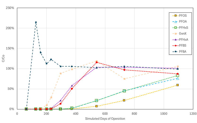
Figure 18-2. Example breakthrough curves for GAC (10-minute empty bed contact time).
Source: Used with permission from Calgon Carbon Corporation.
18.3.1.1 Process Parameters
Two critical concepts for the effective removal of any specific compound using fixed-bed adsorbers are the media’s equilibrium loading capacity and the kinetics of adsorption for the system. The equilibrium loading capacity is the mass of contaminant the media can hold for a given unit mass of media at the contaminant’s influent concentration given a sufficiently long contact time. This is the media’s inherent affinity for the compound of interest. The higher the affinity for a particular compound (equilibrium loading capacity), the slower that compound will work its way through the media, leading to a longer bed life. Regardless of a media’s affinity for a particular compound, it takes some time for a given molecule of the compound once it enters the top of the media to find an adsorption or exchange site. Even for contaminants with an affinity for the sorption media, the sorption rate can be limited by mass- or phase-transfer processes. The evaluation of these rate-limited processes is referred to as kinetics.
If the kinetics of adsorption were instantaneous, then a band of media saturated with a given contaminant would simply move through the bed until it reached the effluent. In such a system, the effluent contaminant concentration would sharply transition from zero to the influent concentration at the point of breakthrough. But the kinetics of reals systems are not instantaneous, so there is always a thickness of media called the mass transfer zone (MTZ) on the leading edge of the saturated band as it moves through the bed. The MTZ is where the adsorption is occurring. The presence of an MTZ can be seen as the gradual, rather than instantaneous, increase in effluent concentration at the initial breakthrough point (Figure 18-2).
Thus, designers of fixed-bed adsorbers must allow for sufficient contact time to account for the kinetics of adsorption (the MTZ) and to provide a bed depth that provides a reasonably long bed life. The convention in the industry is to call this empty bed contact time (EBCT), and it is the media volume divided by the flow rate. EBCTs vary depending on the media used, contaminants present and their influent concentrations, desired effluent concentrations, and levels of co-contaminants (for example, natural organic matter (NOM)) present. Although typical EBCTs per GAC and single-use IX vessel range from 10 to 20 minutes and 1.5 to 3 minutes, respectively, for PFAS removal in drinking water and groundwater pump and treat applications (AWWA 2019; AWWA 2025), bench or pilot testing may validate EBCTs outside of these ranges for specific applications. GAC and IX adsorbers have been used to polish landfill leachate and industrial wastewater effluents. These applications can require significantly longer EBCTs than drinking water or groundwater treatment systems due to higher PFAS and co-contaminant concentrations. Section 18.3.1.3 provides strategies to achieve longer EBCTs.
The velocity of the fluid through the sorption media must be fast enough to avoid maldistribution (or channeling) but not so high as to cause excessive pressure drop. This velocity, often referred to as the linear velocity, superficial velocity, or hydraulic loading rate (HLR), is simply the volumetric flow divided by the vessel cross-sectional area. Typical linear velocities range from 2 to 10 gallons per minute per square foot (gpm/ft2) (5—25 m/h) for GAC and 6 to 18 gpm/ft2 (15—45 m/h) for IX resin (Section 12), but recommended HLRs may vary from this range depending on the application or specific media. The linear velocity dictates the vessel diameter or cross-sectional area, while the EBCT dictates the depth of the media bed.
18.3.1.2 Operational Considerations
When employing adsorbents such as GAC or IX resins, it is critical to exercise caution regarding the potential leaching of unintended toxic constituents, particularly during the initial operational phase. Newly installed media can release trace amounts of contaminants such as arsenic (Gandy and Maas 2004) due to impurities in the raw materials, or nitrosamines, from amine functional groups (Flowers and Singer 2013). These leachates can compromise treated water quality and pose regulatory compliance risks. Procedures for mitigating these issues are discussed in Section 18.3.1.4. Further, during the operation, backwashing of IX resins used for PFAS removal can disturb the established MTZ within the column, potentially redistributing PFAS-laden particles and altering the contaminant concentration profile along the bed depth (Woodard, Nickelsen, and Sinnett 2018). Such disruption may cause breakthrough challenges, complicating the interpretation of monitoring data and masking early signs of adsorbent exhaustion. Furthermore, disturbance of the MTZ can result in transient spikes of PFAS in the effluent, challenging the accuracy of performance assessments and compliance monitoring, particularly for trace-level regulatory limits. Backwashing of GAC can be conducted with minimal impact provided a backwash is conducted on a newly installed bed to stratify it.
18.3.1.3 Adsorber System Configurations
A lead/lag (vessels in series) configuration is often employed for fixed-bed vessels to provide a margin of safety for complying with effluent limitations and to lower the overall media consumption rate. The use of multiple vessels in series permits the lead vessel(s) to become more heavily loaded with contaminants prior to exchanging the media, thus driving the overall media usage rate down. Each time a lead vessel becomes spent, its media is replaced, reactivated, or regenerated, and the vessel’s flow position is moved furthest downstream. While the lead vessel is temporarily offline, flow often continues through the lag vessel(s). The vessel that was formerly furthest downstream is then moved one vessel position upstream in the order of flow. In this mode of operation, the vessel with the cleanest media is always the last vessel in the order of water flow. Provided that the MTZ is small enough to fit within a single vessel, lead/lag operation potentially permits media to be changed out on near complete exhaustion, rather than initial breakthrough, leading to more efficient use of media.
In some instances, a lower cost sorptive media to remove co-contaminants can be used in front of higher cost media specific to PFAS removal. If the required flows exceed what can be treated by a single train of vessels in series, then additional trains can be introduced in parallel to increase total flow rates. Sufficient flow paths and valves must be present in interconnecting piping between multiple vessels in series when the intent is to hard pipe the vessels together and allow any of the vessels to be in the lead position. Strategies to increase the EBCT for a fixed flow rate include increasing vessel size or increasing the number of vessels in series or parallel. Or, for a given treatment system, the EBCT can be increased by decreasing the flow rate. In cases where a single vessel of media is used, sample taps located at 25%, 50%, and 75% of the bed depth, which are widely used in vessels in PFAS service, can be used to assess the extent of breakthrough before PFAS are detected in the vessel effluent. Sample taps can be useful in individual lead/lag vessels as well, enabling better prediction of breakthrough and evaluation of performance upsets.
18.3.1.4 Media Conditioning and System Startup
Fixed-bed sorption media require preparation prior to use, and while specific media manufacturer guidelines should be followed, this section will cover the general steps for both GAC and IX media.
With respect to GAC media, the startup process can be broken down into three distinct steps: the loading and wetting step, the backwashing step, and the conditioning step. The first step, loading and wetting, involves the transfer of the media from the delivery vehicle to the vessel and the soaking of the installed media in clean water. The goal of this step is to displace the entrapped air in the media’s pore structure by soaking the media in water (usually overnight). Once the media is properly degassed, the second step can begin—the backwash step. The goal of the backwash step is to remove the media fines and to stratify the bed by size, with the smaller granules at the top and the larger granules at the bottom. By removing the fines and stratifying the bed, the hydraulics of the system are optimized and the clean-bed pressure drop minimized. In addition, the stratification of the bed by size minimizes the impact to the MTZ a subsequent operational backwash may have. The last step in the process is the conditioning step, which is a slow forward rinse-to-waste process. The goal of the conditioning step is to stabilize the media bed’s effluent pH and remove soluble metals from the finished water stream. Reviewing the manufacturer’s startup procedure is important to understand the volume of water required to commission a GAC system. Note that most media manufacturers also have options available to reduce the volume of water required if there are site constraints.
With respect to IX media, the startup process consists of two steps: the loading step and the conditioning step. Unlike GAC media, degassing IX media is usually not required since it is typically already wetted. Furthermore, there is usually no backwash step for IX media because the risk of media washout is high due to the relatively low specific gravity of the media. There is a conditioning step, which, like GAC, means a slow forward rinse-to-waste of the media. The goal of this conditioning step is to rinse off any manufacturing byproducts, such as nitrosamines, prior to commissioning the system. The conditioning step for IX media typically uses less water than the GAC conditioning step. Like GAC, IX media manufacturers have options available to reduce the volume of water required if there are site constraints. Freshly installed IX columns may cause short-term disruptions in pH or corrosivity of effluent water (see Section 12.2.1.2).
18.3.1.5 Water Quality Impacts and Pretreatment Needs
The matrix of co-contaminants, background NOM, and other water quality parameters often significantly impacts fixed-bed media consumption and performance for PFAS removal applications. Thus, pretreatment of the water is sometimes necessary to mitigate media fouling to extend bed life, and pilot testing is often recommended to accurately account for these impacts. Fixed beds in these applications are designed to sorb dissolved constituents, so prefiltration with 5-micron or 10-micron filters to remove suspended solids is commonly recommended to ensure the most cost-effective use of the media. Precipitation of iron and manganese particles can foul sorption media and can lead to biofouling from iron bacteria. This problem can be mitigated by treatment to reduce iron and manganese concentrations to below the secondary Maximum Contaminant Level (MCL) of 0.3 mg/L (or lower, depending on piloting data). Biocides or sodium hypochlorite are sometimes used to reduce naturally occurring microbial activity upstream of sorbent media that would otherwise result in biofouling. Disinfectant residuals, however, may damage some sorbent media, so consulting the media manufacturer is recommended. Hard water with a positive LSI can result in precipitation of calcium carbonate within the media, which blocks access to sorption sites. Targeting a neutral or slightly negative LSI can mitigate these concerns. Addition of anti-scaling agents such as phosphonates can reduce the risk of scale formation, but it is possible that these anti-scaling agents could compete with PFAS for exchange sites on IX resins (Haupert et al. 2023). In some instances, GAC may provide more flexibility than IX for sites with significant fouling risk due to suspended solids or precipitated metals (for example, iron or manganese) and without a means to pretreat the water because GAC can be backwashed with minimal impact to performance. It is easier to wash out the media and to disrupt the MTZ when backwashing IX resin.
TOC, including NOM, can interfere with the performance of both GAC and IX adsorption of PFAS. Advanced oxidation approaches such as ozonation (Vatankhah et al. 2022) can be used to transform and reduce TOC. However, ozonation and AOP can also increase concentrations of PFAS through precursor transformation, potentially leading to a performance tradeoff for some water compositions. Pretreatment media such as GAC is also used to remove TOC prior to the PFAS treatment media. GAC that is used to remove TOC may have different characteristics (for example, different mesoporosity) than the GAC used to treat PFAS and may be designed for a different EBCT. In general, the impact of NOM on PFAS removal by IX depends on the characteristics of the resin and NOM. For example, removal of PFAS by polystyrene-based strong base IX resins is typically less affected by DOC than polyacrylic-based strong base IX resins that have a higher selectivity for DOC (Hu et al. 2016). The properties of the NOM are important as well: removal of PFAS decreases as the charge density, molecular weight, and aromatic carbon content (hydrophobicity) increase (Boyer et al. 2021).
Many PFAS exist in anionic (soluble) form in the ambient pH conditions commonly encountered in surface and groundwater. Physical adsorption onto GAC of some short-chain PFCAs that have pKas above 3 would be expected to improve as the pH drops and the ionic fraction decreases. PFSAs and long-chain PFCAs have pKas below 2 and are not likely to be impacted by pH (Section 4.3.2). Boyer et al. (2021) summarized the impacts of pH, background inorganic ions, and NOM on the removal of PFAS by IX resins in a comprehensive review. Strong base IX commonly used to treat PFAS are typically robust with respect to direct pH effects, with fixed groups being ionized over pH ranges of most applications. Weak base IX resins, whose charge is sensitive to pH, have generally exhibited a lower capacity for PFAS than their strong base analogs (Liu and Sun 2021; Kassar and Boyer 2023). As noted with GAC, only the charge composition of very short-chain PFCAs is likely to be strongly influenced by pH. Changes in pH also theoretically change the adsorption strength of some NOM fractions. Overall, the potential benefit to manipulating the pH has not been demonstrated to outweigh the added cost and complexity; therefore, GAC and strong base IX systems are commonly employed at ambient pH conditions.
IX resin (specifically anion exchange resin) is most sensitive to the presence of dissolved anionic species, such as nitrate, sulfate, and chloride, which will compete with PFAS for capacity on the IX media (Wahman et al. 2023). Waters with high salinity may be particularly challenging to treat with IX, and practitioners may consider testing other media in such situations. Pretreatment to remove major inorganic anions (for example, high-pressure membranes or demineralization by IX) is not commonly practiced and would be unlikely to make IX treatment more cost-effective overall. However, knowing the concentrations of major anions in the water to be treated is still valuable because that knowledge can be used in conjunction with modeling (Section 18.3.2.1) to aid in planning and design of pilot systems.
18.3.1.6 Media Description and Properties
IX Resins
Polymer-based IX resins used for PFAS treatment morphologies can be divided into two classes based on pore structure: gel-type and macroporous. The pores of gel-type resins are small enough (usually 1–2 nm) that they do not scatter light, giving these resins a translucent appearance. Macroporous resins, by contrast, usually have pore sizes larger than 20 nm, and are opaque. Gel-type resins usually contain more functional IX sites by volume than otherwise equivalent macroporous resins, which may lead to higher PFAS adsorption capacity for some applications. However, the pore and crosslinking structures in macroporous resins make them more rugged than gel-type resins and lead to faster exchange rates under some conditions. Accordingly, macroporous resins are often considered for applications involving regeneration or challenging water conditions. For example, in waters where biofouling potential is high, the ability to chlorine shock macroporous resin is key to avoiding costly media replacements. If the feed water contains a low level of chlorine residual (for example, 0.2–0.7 ppm, on average, from greensand filters continuously), using a macroporous resin can avoid the addition of a dechlorination step (such as sodium bisulfite addition). Macroporous resins are also expected to be more resistant to iron and manganese fouling than the gel-type resins, which may reduce the need for oxidant-based pretreatment in the first place.
IX resins of different polymer compositions (polystyrene and polyacrylic), pore structures (gel or macroporous), and functional groups (quaternary ammonium, tertiary amine, complex amino) have been used to remove PFAS. Most studies comparing IX resins have been done on PFOS (Boyer et al. 2021) and have found that polyacrylic/gel/weak base or polyacrylic/macroporous/strong base (type I quaternary ammonium functional group) resins have the highest capacity (Chularueangaksorn et al. 2013; Deng et al. 2010; Schuricht et al. 2017; Schuricht et al. 2014; Zaggia et al. 2016). When considering the removal of short- and long-chain PFCAs and PFSAs, del Moral et al. (2020) found that a polystyrene/macroporous/strong base IX resin (triethyl functional group) outperformed a polyacrylic/macroporous/strong base IX resin (triethyl functional group).
GAC Media properties
The raw materials used to manufacture commercially available GAC primarily consist of bituminous and sub-bituminous coals, wood, and coconut shells. The adsorption pore structure and certain physical properties such as abrasion and inorganic mineral content of an activated carbon product are inherited from the raw material used to make it. For example, bituminous coal and coconut shells yield harder and denser activated carbon with more microporous structure compared to wood or sub-bituminous coal.
Every activated carbon product has a distribution of pore sizes, often categorized into micro (<2 nm), meso (2–50 nm), and macro (>50 nm) fractions. Although most of the adsorption occurs within the micro- and mesopores, macro porosity is important because it serves as a conduit to transport contaminants to the adsorption sites. McNamara et al. (2018) demonstrated that re-agglomerated, bituminous coal–based activated carbon outperformed coconut-based activated carbon for PFAS removal due to an enhanced transport pore network. During the manufacturing process, the raw materials used are crushed and processed and the GAC is screened to meet certain mesh size specifications. Common GAC mesh sizes employed in water treatment and their respective (US Mesh) size distributions are 12 x 40 (0.43–1.7 mm) and 8 x 30 (0.60–2.36 mm). Specifications for GAC products used in the drinking water industry are provided in AWWA B604 (AWWA 2018).
GAC/IX Comparisons
Many studies have been conducted comparing the PFAS removal performance of GAC and IX resin (Liu et al. 2022; Zeng et al. 2020; Murray et al. 2021; Tajdini et al. 2025). Although most studies have concluded that PFAS adsorption capacities and media lives for IX are greater than equivalently sized GAC beds, pilot-scale testing with site water as well as an evaluation of the total capital and operating cost on a net present value (NPV) of cost basis is recommended to select the most cost-effective remedy for an application. Numerous studies have confirmed two common trends in the removal of PFAS using sorbent media (Zeng et al. 2020). First, the longer chain PFAS within the same class adsorb better than the shorter chain PFAS. For example, in the class of perfluoroalkyl sulfonates, PFOS (C8) adsorbs more strongly than PFBS (C4), and in the class of perfluoroalkyl carboxylates, PFOA (C8) adsorbs more strongly than PFBA (C4). Second, the sulfonates adsorb better than their corresponding carboxylates of the same chain length. For example, PFOS adsorbs better than PFOA. This trend is especially pronounced in PFAS-selective IX resins, which often have even higher affinity for PFBS than for PFOA. Although IX resins, including regenerable IX resins, have higher capacity for short-chain sulfonate PFAS than GAC, they are considerably more expensive on a unit basis. It is also possible that the use of varying media in series can extend media lifetime by removing competing co-contaminants or water constituents such as organic matter. Due to the complexities of assessing relative performance and cost of GAC and IX systems, a site-specific economic evaluation of both types of media is recommended. Additional information about mixed media treatment systems can be found in Section 18.3.2.3.
18.3.1.7 Media Reactivation and Regeneration
Thermal GAC Reactivation
Although the terms “regeneration” and “reactivation” are sometimes used synonymously, there is a distinction. GAC reactivation is a thermal process that returns the GAC to a near virgin state. GAC reactivation is commercially available at large-scale, with about 17 facilities currently operating in the US (USEPA 2024). When spent GAC is returned to a reactivation facility, it enters a furnace where residual moisture is driven off and volatile contaminants are vaporized as the first step. Calcination and pyrolysis then occur, which char organics not previously volatilized. In the final step, steam gasification removes some of the carbon atoms within the biochar to return the activity level of the carbon to a near virgin state. The bulk of the adsorbed organic mass is thermally destroyed within the furnace, and emission abatement systems are used to capture and destroy remaining organics, acid gases, and particulate matter. The fate of adsorbed PFAS through a reactivation facility has been studied (see Section 18.3.3). GAC reactivation consumes between 15% and 30% of the media mass (USEPA 2024) and requires this amount of virgin media makeup for each reactivation cycle.
Reactivated GAC has demonstrated similar PFAS removal efficacy when returned to the original facility, but lower PFAS removal efficiency when using general-pool reactivated carbon from unknown origin (McNamara 2018). General-pool reactivated carbon should not be used for drinking water applications due to potential contamination from non-drinking-water sources. Sites considering GAC reactivation for PFAS treatment should contact reactivation facilities to see if they merit a site-specific reactivation contract (typically at least 80,000 pounds per change-out as of 2023 communications) (Barr Engineering and Hazen and Sawyer 2023). Consult activated carbon reactivation vendors to confirm minimum required quantities, as batch quantities less than 80,000 pounds may be possible.
GAC reactivation offers a similar service to high-temperature incineration, with about 17 facilities operating in the US and lower costs than high-temperature incineration (USEPA 2024). GAC reactivation can be used as a disposal method if facilities are replacing carbon with virgin carbon and reactivated carbon is returned to a general pool for resale. Alternately, facilities can accept reactivated carbon back for reuse. Using reactivated GAC offers a significant environmental benefit: a reduction in global warming potential of up to 80% compared to virgin carbon (Vilen, Laurell, and Vahala 2022). Destruction efficiencies of greater than 99.99% of targeted PFAS have been demonstrated through GAC reactivation (DiStefano et. al 2022), though full defluorination is difficult to demonstrate due to analytical limitations in closing the fluorine mass balance. Relative to high-temperature incineration with virgin media replacement, GAC reactivation and reuse is estimated to use less than half as much energy and incur less than half the operational expense (Ling et al. 2025).
GAC Regeneration
Regeneration refers to the process of partially restoring the capacity of a spent GAC, typically within the vessel, and uses either thermal (for example, steam) or chemical means to desorb contaminants in liquid-phase applications. Contaminants desorbed from the GAC must then be captured and destroyed or disposed by other means. Regeneration processes have been largely unable to completely restore the adsorption capacity of GAC and, therefore, experience decreasing efficiencies as the regeneration cycles proceed (Vakili et al. 2024). In-vessel GAC regeneration uses a basic solvent solution (Siriwardena et al. 2021). The spent regenerant solution is distilled and the resulting PFAS extract is proposed for destruction with supercritical water oxidation (SCWO) (Scheitlin et al. 2023), but could also be destroyed using other liquid destruction technologies, as further discussed in Section 18.3.3. The number of regeneration cycles a single vessel of these media can undergo may be limited, in part due to media degradation. However, application of in-place chemical regeneration of standard, bituminous GAC media has not yet been demonstrated widely on a commercial scale.
Several other technologies are being evaluated at lab-scale and pilot-scale for GAC regeneration, including hydrothermal alkaline treatment (HALT) regeneration (Soker et al. 2023), microwave regeneration (Gagliano et al. 2021), and plasma reactivation (Bailey 2021).
IX Regeneration
In some treatment systems, the adsorptive treatment media is regenerated within the vessel to replenish capacity. In situ regeneration of IX media for PFAS treatment for non-drinking-water applications is commercially available and has been used in cases of high PFAS influent concentrations or treatment of short-chain or ultrashort PFAS that would otherwise require very frequent media exchanges (Woodard, Berry, and Newman 2017; Woodard, Nickelsen, and Sinnett 2019, Kempisty et al. 2024). The book chapter by Woodard, Nickelsen, and Sinnett (2019) offers a comprehensive overview of regenerable IX resins for PFAS removal, including mechanisms of removal, importance of water quality analysis, key design parameters, loading and regeneration cycle data sets, and economic considerations. A case study demonstrating the use of regenerable IX resins, including a system diagram, is available in Section 15.2.2.2. Regenerable resins tend to be macroporous, rather than gel-type, because of the importance of ruggedness and fast kinetics during regeneration (Liu and Sun 2021). Some regenerable resins have lower capacities (Ellis et al. 2022) or require a longer EBCT to achieve similar capacity to single-use PFAS-selective resins, but this could be offset by O&M cost savings associated with on-site regeneration over off-site disposal (Ling et al. 2025).
Strong base IX regeneration involves the desorption of PFAS from the resin with a solvent brine solution that breaks both the hydrophobic and anionic interaction of the PFAS with the media. Multiple trials of regeneration using various combinations and concentrations of salts and solvents were conducted in (Crimi et al. 2023). These trials concluded high concentrations of alcohol solvents, for example, 75% by volume, and sodium chloride at 2% resulted in the most efficient and complete desorption of PFAS from the media. Research studies have also shown that even IX resins that are typically considered to be “single-use” resins can also be regenerated using 90% methanol brines (Ellis et al. 2025). After regeneration, the solvent is distilled for continued regeneration cycles and a PFAS concentrate known as a “still bottom” is the residual waste product of the process that can be further handled. Management of spent residuals is discussed further in Section 18.3.3.
Currently, no state agencies permit solvent regenerated IX (or GAC) systems for PFAS treatment of drinking water (Ling et al. 2025). Regenerable IX has been reused in full-scale PFAS remediation systems since 2018. Five years of performance data from a full-scale system demonstrated continuous use of IX resins without performance deterioration (Kempisty et al. 2024). Potential application scenarios for media regeneration include on-site regeneration and solvent recovery, on-site regeneration with off-site solvent recovery, and off-site regeneration of spent media vessels. Advantages of regenerable IX systems include reuse of the resin, reduced waste generation and associated liabilities, reduced size requirement of PFAS destruction technology, and lower operating costs, particularly when short-chain or ultrashort PFAS removals are required. An important consideration for life cycle cost is that high concentration solvents trigger the need for fire protection and intrinsically safe equipment. Moreover, the regeneration equipment itself represents important additional capital costs. The opportunity over time is cost savings associated with nonregenerable media replacement. Life cycle cost assessment (LCA) in Hagelin et al. (2022) suggested an expected return on those capital investments may occur during the time-horizon of a typical groundwater remediation system.
On-site or mobile regeneration of resin, typically using brines and/or solvents, provides the benefit of not having to physically remove and change out spent resin. Concentrated liquid produced during regeneration requires disposal. The primary waste product evolved from regenerable IX or GAC systems is the still bottom which contains high concentrations of PFAS and the regenerant salt. This material can be further concentrated with media in a process known as super-loading, which exposes the still bottoms to a mixed media bed with long contact times to achieve equilibrium isotherm conditions (case study provided in Section 15.2.2.2; SERDP ER23-8391; Haeglin et al. 2022). Alternatively, the resulting still bottoms can be disposed of via traditional high-temperature incineration, SCWO, or an emerging destruction method such as HALT, plasma, or electrochemical treatment (Singh et al. 2020; Maldonado et al. 2021; Liang et al. 2022; Pinkard et al. 2024; Higgins et al. 2025), depending on the treatment equipment’s ability to handle the still bottom salt content. Large-scale implementation could leverage a “hub-and-spoke” model with a regional regeneration and PFAS destruction facility servicing multiple facilities using IX resins, where vessels or media are sent to centralized facilities for regeneration and PFAS destruction (Kempisty et al. 2024). The additional capital costs associated with IX regeneration should be evaluated with an LCA; the payback period can be as little as 2 years or can be determined not to be feasible if the conditions do not provide an acceptable payback (for example, low flow rates, infrequent change-outs, or easily obtained treatment objectives). Similar approaches are being used for the regeneration of GAC and novel adsorbents (ESTCP Projects ER23-8379, ER23-8391), although the number of regeneration cycles these media can undergo may be limited. On-site or mobile electrochemical oxidation has also been used for the regeneration of GAC treating landfill leachate. As an example, one vendor uses an on-site solvent-based GAC regeneration process with a regional hub to process spent solvent for recovery reuse while separating desorbed PFAS for destruction at the hub using SCWO (DiGuiseppi et al. 2024). Hubs may be set up as centralized waste treatment facilities(USEPA 2025). Where regeneration solutions (additives) are used, the ability to demonstrate their removal from the media/vessel prior to reinstallation for treatment should be evaluated. Destruction of regeneration brines is further discussion in Section 18.3.3.
18.3.2 Performance Evaluation
18.3.2.1 Fixed-Bed Adsorption Models
The most accurate way to predict the breakthrough behavior of PFAS in fixed-bed adsorbers is to conduct bench- or pilot-scale column tests using water from a particular site. Conducting these tests, however, can be time-consuming and expensive. A faster, although often less accurate, method of assessing fixed-bed performance is to use modeling. A publicly available model from the USEPA’s “Water Treatment Models” GitHub site (USEPA 2021) using the pore and surface diffusion model can incorporate the effects of fouling and predict performance of GAC. This model is based on the AdDesignS (Michigan Technological University, Houghton, MI) adsorption design software that was released into the public domain as part of the USEPA’s Environmental Technologies Design Option Tool (ETDOT) (USEPA 2023). The challenge in using models such as this is that many of the model inputs parameters are not widely available and are quite difficult to determine (Burkhardt et al. 2022). Ideally, model inputs would include single solute Freundlich isotherm values of K and 1/n, external mass-transfer coefficients, internal diffusion coefficients, parameters for background NOM, and fouling factors for equilibrium capacity and kinetics (Burkhardt et al. 2022). PFAS isotherm parameters are sparse in the literature, however, some theoretical methods can estimate K and 1/n for PFAS with some success (Burkhardt et al. 2023]). Burkhardt et al. (2022) fit a pore and surface diffusion model to RSSCT breakthrough curves and then used the model to predict the impacts of changing fixed-bed parameters such as bed diameter, flow rate, and influent concentrations. Some activated carbon vendors have their own predictive models and databases. However, these vendor-specific tools are generally proprietary and not available to decision makers outside of consultation with vendors. The advent of machine learning methods has yielded novel approaches to estimating GAC performance in PFAS applications. For example, Koyama et al. (2024) compiled a data set of published PFAS breakthrough curves on GAC adsorbers and developed machine learning models using GAC characteristics, PFAS properties, and water quality parameters to predict throughput to 10% breakthrough (BV10). Although the machine learning model developed by Koyama et al. had mean errors of roughly 32% on BV10 and does not produce whole breakthrough curves, it is still a potentially useful tool for estimating the duration of GAC pilot studies.
Modeling tools for predicting the performance of IX resins for PFAS removal are few and far between—especially freely available or open-source models. As with GAC, various media vendors and consultants have proprietary IX models for use internally, but these models are not typically published in peer-reviewed literature. It is accordingly difficult to comment on them because the underlying theory of their operation is unknown.
Use of empirical breakthrough curve models is common practice in literature and can be quite useful for interpolating data and comparing breakthrough curves among competing adsorbents. However, breakthrough curve models that neglect mass transport mechanisms or use purely empirical isotherms have difficulty correctly predicting the effects of changing system EBCT or variability in PFAS concentrations (Haupert, et al. 2021; Haupert et al. 2023), which are common concerns when interpreting pilot data and designing full-scale systems.
The USEPA has developed an IX performance model that closely follows the mechanistic conventions of the GAC model in AdDesignS, incorporating mass transfer resistances and combining them with multicomponent IX isotherms (Smith et al. 2023; USEPA 2021). This model explicitly includes competition effects from multiple ions in solution (Figure 18-3). Using IX isotherm parameters from the literature (Fang et al. 2021; Wahman et al. 2023), it is possible to make predictions about the impact of changes in commonly occurring anions (such as chloride, sulfate, and nitrate) on expected PFAS treatment performance. Unlike the GAC models, the IX models developed by USEPA do not currently have well developed methods for handling competition from NOM. Although the model can be used to estimate NOM impacts on performance in pilot data (Haupert et al. 2023), prediction is not yet rigorously possible. Some empirical, quantitative structure-property relationships (QSPRs) and pseudo-single solute models for estimating NOM effects on PFAS adsorption on IX systems have been developed for specific waters using AdDesignS (Cheng et al. 2025), but NOM is difficult to characterize and waters with similar TOC/DOC levels can have very different IX performance impacts (Tajdini et al. 2023). It is possible that additional research with carefully controlled water quality—for instance, with the use of lyophilized NOM in laboratory column studies (Abulikemu et al. 2022)—will shed light on the underlying mechanisms of NOM interference on ion exchangers. Despite this limitation, it is still possible to use these models to make predictions about the effects of changing PFAS concentrations and changing operational parameters such as EBCT.
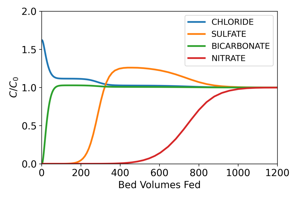
Figure 18-3. Example output of USEPA’s IX model (USEPA 2021) showing influent-normalized effluent concentrations of commonly occurring anions in drinking water for an example system (Haupert et al. 2023). This output demonstrates the model’s ability to predict chromatographic effects from displacement.
18.3.2.2 Summary of Testing Methods
As discussed in Section 18.3.1, general guidelines exist to help engineers design adsorption-based systems for PFAS removal. The media’s performance and change-out frequency, however, cannot be generalized, as it is dependent on each site’s water quality and proposed design. As a result, performance testing or evaluation of historical treatment data from analogous applications should be completed at each site to select the most cost-effective adsorptive media, including consideration of reactivation/regeneration, disposal, and/or replacement costs. Testing allows owners to make data-driven decisions regarding which technology is optimal for their scenario by looking at both performance and expected life cycle costs.
When it comes to adsorptive media, feed-water quality can have a significant impact on both operability and performance with respect to PFAS removal. For example, water sources with elevated levels of anions, such as sulfate and nitrate, tend to reduce media lifetime for IX resins. Similarly, water sources with elevated levels of TOC tend to be challenging for GAC media. Furthermore, sources with steady water quality (for example, groundwater) are usually well suited for lab tests. On the other hand, surface waters used for drinking water, which tend to see seasonal changes to their water quality, are not well suited for lab tests. These are some of the factors that need to be considered when evaluating different adsorptive media technologies and performance test options.
It is important to note that the term “feed water” does not necessarily mean the site’s “raw water.” PFAS treatment by fixed beds in wastewater and drinking water systems tends to be tertiary processes, within those systems, they are downstream of conventional treatment. Where the PFAS system is tied into the process can have a significant impact on the performance of the adsorptive media. For example, antiscalant from an upstream air stripper process may interfere with PFAS adsorption in downstream IX unit operations (Haupert et al. 2023). The same study found that low levels of VOCs in the feed water did not have a measurable impact on the performance of the GAC with respect to PFAS removal. Therefore, understanding the feed water quality to the future PFAS removal system can help owners select which adsorptive media to evaluate in their performance tests, and it is important to conduct testing on water that has already been subject to all intended pretreatment. More detail about applicable pretreatment strategies can be found in Section 18.2.3.
There are four main performance test options an owner can pursue when investigating different adsorptive media technologies for PFAS removal. The first two are lab-based tests—the isotherm test and the RSSCT. The other two are field-based tests—the pilot test and the full-scale demonstration test. As shown in Table 18-3, each option has advantages and disadvantages that will be discussed in more detail in the following subsections.
Table 18-3. Summary of performance test options for evaluating adsorption-based technologies
| Test Type | Relative Time to Completion | Relative Cost | Ability to Compare Media? | Predictability of Full-Scale Performance |
|---|---|---|---|---|
| Isotherm | Shortest | Least | Yes | Poor |
| Rapid Small-Scale Column Test | Moderate-low | Moderate-low | Yes1 | Moderate2 |
| Pilot | Moderate-high | Moderate-high | Yes | High3 |
| Full-Scale Demonstration | Longest | Highest | No4 | Best |
1 The RSSCT method has historically been used to compare the performance of GAC media. Although work is currently being done to modify the test for IX media, an industry consensus on the method has not been reached.
2 GAC media RSSCTs for evaluating PFAS removal have been shown to either underpredict or overpredict the full-scale performance (Cheng and Knappe 2024; Hopkins and Knappe 2024; Liu, Liu, and Sun 2024). This issue is discussed in more detail in Section 18.3.2.4.
3 The pilot study design plays a major role in the scalability of the results.
4 Due to the scale of these tests, typically only one media is evaluated.
18.3.2.3 Isotherm Tests
One way to evaluate adsorbent media is via batch mode bench-scale experiment, whereby a known volume and concentration of PFAS-containing water is mixed for a set exposure time with a measured mass of adsorbent media to determine changes in the water’s PFAS concentration. Typically, these batch tests are repeated with the same influent water (concentration and volume) but using varying doses of the adsorbent media. The data are then analyzed using an appropriate adsorption mathematical model (for example, Freundlich, Langmuir,) to develop an isotherm curve—a mathematical function relating the amount of PFAS adsorbed on the media to the remaining concentration of PFAS in the water at equilibrium.
In practice, it is common to use isotherm results as a means of identifying media that can remove the target contaminant for an application. Adsorbents showing the best performance can then be selected for further testing by RSSCTs or pilot tests. Batch isotherm tests using carefully controlled, synthetic waters have been used to obtain relative affinities for PFAS and common inorganic ions on some common IX resins (Wahman et al. 2023). These relative affinities can be used in conjunction with isotherm tests to make predictions about the effects changing concentrations of PFAS or common inorganic ions (for example, chloride, sulfate) have on IX performance. However, because NOM impacts on IX isotherms are still not well understood, the isotherm test is not able to rigorously predict PFAS breakthrough curves in practice. This limitation, along with the time, expense, and expertise needed to conduct such detailed batch experiments, means that these efforts are typically conducted by researchers rather than practitioners.
It is important to note that isotherm results provide an adsorbent media’s capacity for PFAS at equilibrium. Notably the appropriate time to reach equilibrium in isotherm batch testing can vary with different media and different adsorbent doses (Wahman et al. 2023) and should be considered during experimental design. It is therefore important to confirm that bottle isotherm tests have reached equilibrium for proper interpretation of results. It is important to note that the kinetics of adsorption in bottle isotherm tests do not necessarily reflect the kinetics in column process. For this reason, isotherm results should not be used by themselves to extrapolate full-scale performance.
In situations where owners have time or budget constraints precluding further testing, isotherm results can be used with column performance models (for example, AdDesignS (USEPA 2023)) to obtain high level, estimated time to breakthrough for PFAS of interest. Although this approach is not the most accurate, it can provide a rough initial method of comparing adsorbent media performance to assist in planning. If the owners find themselves in this situation, they should keep three things in mind. First is to make sure they use their site’s actual water, rather than synthetic water, for their testing to increase the representativeness of their results. If the site’s water source is highly variable, the owner may want to run two isotherms (for example, winter and summer) to understand how the changes in water quality impact the adsorbent media’s performance. Second, during the batch tests, any co-contaminants of interest also in the test water can be monitored. This allows owners to understand any potential added water quality benefits associated with adsorbent media. Last, water quality impacts (for example, fouling) and operational complexities (for example, backwash frequency) cannot be assessed in a batch test. Visiting a facility that already uses the adsorbent media(s) being evaluated can provide some operational knowledge to assist with this limitation of the isotherm test.
18.3.2.4 Rapid Small-scale Column Tests (RSSCTs)
A second lab-scale performance test available is the RSSCT. Originally developed around GAC media, the procedure for this test can be found in ASTM D6586-03, though it has not seen significant updates for PFAS applications (ASTM 2021). Due to the lack of industry consensus with respect to the IX RSSCT, some vendors and consultants recommend using the ASTM RSSCT method only with GAC media. With that said, it is imperative that practitioners understand that small errors in the test setup can lead to significant impacts on the results and conclusions of the test. To aid utilities in obtaining representative and accurate media performance relative comparison from RSSCT tests, here are some general guidelines to follow:
- The calculations in the ASTM D6586 RSSCT method should be followed.
- Ground media must be analyzed using sieve analysis (for example, alpine air jet sieve) to confirm size before testing; scaling should be recalculated based on results for each media.
- Full-scale mean particle diameter assumptions should be acquired from the media manufacturers.
- Small-scale column fill weight and volume should agree with the full-scale apparent density of the material tested.
Assumptions concerning the relationship between intraparticle diffusivity and carbon particle size can have a significant impact on the accuracy of RSSCTs to predict full-scale breakthrough (Hopkins and Knappe 2024). Hopkins and Knappe (2024) concluded that RSSCTs assuming constant diffusivity (CD) have shorter run times and are more accurate than proportional diffusivity (PD) at predicting the onset of PFAS breakthrough, but the shape of the breakthrough curve needs to be adjusted using the pore and surface diffusion model. An alternative presented by Hopkins and Knappe (2024) is to use a proportionality constant somewhere between CD and PD. In contrast to PD-RSSCTs, neither Hopkins and Knappe’s (2024) method nor CD-RSSCTs need further adjustments to the breakthrough data need to be made to account for the effects of fouling.
RSSCTs provide a more accurate representation of adsorptive media performance, because they are operated under a scaled down HLR and EBCT, unlike the isotherm tests. As such, this is a great option for utilities that are evaluating multiple adsorbent media and want to select the best performing one(s) for further testing. Like the isotherm test, RSSCTs rely on a grab sample of water for completing the test. This means that results are tied to the water quality of that specific grab sample, which may or may not be representative of the water source as a whole or for every season. For this reason, the same grab water sample should be used as the feed water to each media RSSCT column being evaluated to minimize variables during the assessment. RSSCT run times and sample water volumes will vary depending on multiple factors, and typically range from 5 to 90 days and 25 to 55 gallons.
Results of the RSSCT can be applied directly to draw qualitative comparisons between media performance but should not be used in lieu of pilot testing for direct scale-up. RSSCTs capture performance on only a small sample of water from the affected site and may not be representative of long-term trends in water quality. RSSCT theory assumes similitude between the full-size and reduced-size adsorptive media to predict full-scale performance. From a morphological standpoint, this seems a reasonable assumption for GAC because both full-size and reduced-size GAC have been milled and have irregular particle shapes. However, Abulikemu et al. (2023) noted differences in specific surface area and surface oxygen content between GACs milled with different grinding methods. Differences in these properties were also observed in different size fractions even with a consistent milling method. Variability in PFAS adsorption in bottle isotherm tests has also been reported to depend on the size of milled GAC particles (Abulikemu et al. 2025). The effects of milling might be even more important for IX resins. Full-size IX resin beads are typically smooth, uniform spheres, but milling resin beads changes the morphology to irregular shapes. It is not yet clear how this change in morphology might affect correspondence between RSSCTs results and pilot-scale IX behavior, though this is being actively studied in academia today.
Many studies have shown discrepancies between RSSCT predictions and pilot or full-scale performance, whereby sometimes they underpredict and sometimes overpredict performance (Cheng and Knappe 2024; Hopkins and Knappe 2024; Liu, Liu, and Sun 2024). This is especially true for IX RSSCTs. The current usefulness of this performance test for IX mostly lies in supporting media selection for pilot studies, rather than in substituting for them. This situation may change in the future as researchers and the water industry continue to research IX RSSCT methods and adsorption mathematical models.
GAC RSSCT test results can be used in tandem with column performance models (for example, AdDesignS) to obtain midrange full-scale bed life predictions for PFAS of interest. This option should be explored for utilities that lack the time or resources to pursue pilot testing. For sites with variable water quality, conducting two RSSCTs (for example, winter versus summer, or wet versus dry) is recommended to capture seasonal variations in testing. Although the accuracy of these RSSCT data–calibrated mathematical models is not as high as pilot testing, it can still provide good information for operations budgeting purposes.
18.3.2.5 Pilot Tests
Unlike the previous two performance tests discussed, pilot testing can provide both media performance comparisons and full-scale bed life predictions accurately for adsorption media. Although more time- and labor-intensive, pilot tests can capture water quality fluctuations, operational complexities such as fouling and backwash frequency, and PFAS removal performance simultaneously. It is important to note that the accuracy of the results will heavily depend on the pilot’s design as compared to the proposed full-scale system.
The first step in the pilot testing process is to develop a robust test plan that considers the site’s water quality, the media manufacturer’s recommendations, and the pilot equipment’s limitations. There are six main components to a good pilot test plan: feed-water considerations, media selection, column design, monitoring plan, project timeline, and data analysis. Table 18-4 summarizes some of the common questions that should be addressed for each component.
Table 18-4. Components of a good pilot test plan 1
| Component | Topics/Questions |
|---|---|
| Feed Water |
|
| Media Selection |
|
| Column Design |
|
| Monitoring Plan |
|
| Project Timeline |
|
| Data Analysis |
|
1 Note that this list is not exhaustive and is meant as a general guideline.
As previously mentioned, the accuracy of the results of the pilot test depends heavily on the design of the pilot column, namely the selected HLR and EBCT. For GAC media, there are two main paths for sizing the column—targeting the full-scale HLR or targeting the full-scale EBCT. Both parameters are important in adsorption, with the MTZ length and shape being more strongly impacted by the selected HLR. Although the ideal pilot would match both full-scale parameters, this is usually not feasible in practice due to the larger sized pilot systems and resulting long testing durations required. Note that pilot-scale evaluations are typically scaled using the design or permitted flow for the facility rather than the average day flow.
When the pilot column is designed to mimic the full-scale EBCT, run time to breakthrough tends to be extended and the resulting HLR is usually significantly less than what the full-scale system would experience. This setup may lead to results that overpredict performance. Alternatively, when the pilot column is designed to mimic the full-scale HLR and the pilot column length is less than the full-scale bed depth, run time to breakthrough tends to be minimized and the resulting EBCT is usually a fraction of the full-scale system. Essentially, the media in the pilot column would be representative of a core sample taken from a fraction of the full-scale bed depth (for example, first 3 ft of media of a 12 ft bed depth). Under this scenario, the results may underpredict performance (more conservative) because the column essentially represents a cross-section of the full-scale bed. Although both options can provide good results, it is important to remember that the goal of a pilot test is to achieve contaminant breakthrough (at least 50%) in a reasonable amount of time. Thus, the recommended setup for pilot tests is to size the column matching the full-scale HLR.
Equally important to the column design is selecting the locations and parameters to monitor during the pilot test. For GAC columns, it is recommended to monitor PFAS, as well any co-contaminants or water quality parameters of concern, such as TOC or VOCs. For IX columns, it is recommended to monitor PFAS alongside anions (for example, chloride, sulfate, nitrate) and metals (for example, iron, manganese). If the feed water contains an oxidant or turbidity, those can also be monitored through the study. Pilot-scale columns are typically anywhere between 2 and 6 inches in diameter, meaning the risk of channeling while sampling can be significant. To minimize risk of channeling, remember to collect samples using low flows through the bottom tap of a column. Ensuring that the column diameter is greater than eight times the average particle diameter of the media is also important for reducing channeling and wall effects (Knappe et al. 1999). If a pilot test consists of a single column, collecting samples from intermediate points along the column depth would be appropriate provided the column length is sufficiently long to contain the MTZ. Weekly PFAS sampling is recommended, alongside twice a week or weekly water quality monitoring samples. Samples should be collected from both the influent and effluent for proper analysis at the end of the study, and care should be taken to minimize sources of external contamination while collecting samples. Consider collecting samples in the opposite direction of flow for columns installed in series to avoid or minimize cross-contamination.
Once a robust test plan is developed, the next step is to procure the necessary equipment and media for the test. A few media manufacturers can provide piloting equipment, and most will provide their media for testing at little to no cost provided the results for their media are shared. The media manufacturer’s recommended loading and startup procedures should be followed to minimize the risk of issues either with pilot operations or data analysis later. Once the system is online, it is important to track the column pressure or pressure drop, flow rate, and throughput daily. Additionally, the column is recommended to be operated to at least 50% breakthrough, because the shape of the breakthrough curve along with the operating parameters monitored daily are essential for determining media performance and scaling up the results.
At the end of the study, the PFAS and operations data should be compiled and used to create breakthrough curves (Figure 18-2). When comparing media performance across multiple types of media, it is recommended to modify the breakthrough curves prior to analysis. Instead of using operation time or bed volumes processed in the x-axis, use gallons treated or days in operation instead. The modified breakthrough curves can then be used to accurately compare the performance of tested media.
When the full-scale HLR is matched, this means that there is similitude between the number of bed volumes to initial and 50% breakthrough between the pilot column and the full-scale system. What changes is what one bed volume represents at each scale. For example, 1 bed volume in a 4-inch diameter pilot column with 3 ft of GAC media is approximately 2 gallons of water treated. In a 12 ft diameter, 40,000 lb vessel running at the same HLR, one bed volume is approximately 10,000 gallons of water treated. Therefore, if at the pilot-scale initial detection was at 30,000 bed volumes and 50% breakthrough at 45,000 bed volumes, then those same bed volume values are expected for the full-scale system. The change is that while the pilot treated only 60,000 gallons of water to initial detection (2 gal x 30,000 bed volumes), the full-scale system would instead treat 300 million gallons of water (10,000 gal x 30,000 bed volumes). Care should be taken when trying to compare performance between different sorption media with respect to the number of bed volumes treated before reaching an established breakthrough criterion. An example would be comparing IX and GAC, which typically have significantly different bed volumes. In this case, it is advisable to compare the performance based on a normalized measure such as pounds of media per million gallons treated.
For GAC media, the pilot test results can be combined with mathematical modeling software (for example, AdDesignS) to improve the accuracy of the pilot results and evaluate different flow conditions not investigated at the pilot scale. A few GAC media manufacturers offer this service if the pilot data are shared. Looking at AdDesignS as an example, the modeling software can be calibrated to the site’s pilot results using a combination of influent data (which may be variable in time) and x and y points, where x is days in operation and y is percent breakthrough. Once the model is calibrated to the pilot results, it can then be used to simulate full-scale performance for a more accurate estimate to minimize the impact of the pilot design not matching both the HLR and EBCT at full-scale. Additionally, the model can also be used to predict performance at other flow conditions such as minimum day flow, average daily flow, and peak hourly flow. These additional simulations can provide important information regarding yearly carbon usage for a more well-rounded life cycle costs assessment. Note that the media manufacturers who supplied the media for pilot testing can provide budgetary price for media disposal, which should be considered during the LCA. Other items that should be considered when comparing pilot test results are operability (for example, frequency of backwashing), site requirements (for example, footprint), and complexity (for example, operator training), among others.
18.3.2.6 Multi-media Pilot Tests
New multi-media treatment processes are being considered now for PFAS applications. One such novel approach is GAC followed by IX resin. The idea behind this combination is for the GAC media to protect the downstream IX media (for example, oxidants, metals, organic compounds, biofouling), thus extending the life of the more expensive IX media with respect to PFAS. In these full-scale systems, the GAC media is exchanged at a predetermined breakthrough point, and the IX resin is kept as a polisher vessel rather than rotate vessel positions. The operation of these dual media systems is complex, because it requires more monitoring and more care when operating the system. Pilot testing these novel configurations can provide some insights into full-scale performance but typically cannot be properly scaled up. This is because the pilot test would require the GAC media column to be replaced at the predetermined breakthrough point each time it is reached to truly evaluate the bed life for the IX media. Because fresh GAC media is placed online at regular intervals, the timeline for these projects typically exceeds the available time a site has. So, while the pilot may not directly yield the expected bed life for the IX media within the project timeline, it can provide confirmation that the IX system works as intended along with a conservative estimate of the minimum expected bed life. It can also provide information on how well the GAC protects the IX media, and how often the GAC media may need to be exchanged.
18.3.2.7 Full-Scale Demonstration Tests
Although rare, full-scale demonstration tests can be conducted to determine the effectiveness of an adsorptive media for PFAS removal. This style of testing is typically used after one adsorptive media has been selected and installed and is more commonly seen with GAC media. Remediation systems commonly go through an initial startup process to verify treatment system performance and to monitor the impact of geochemical parameters on the operation of the system. During this process, more thorough monitoring and testing is commonly conducted than during the long-term operational program. For example, sorption beds that have multiple sample taps along their depths can be sampled initially to gauge how quickly the bed is exhausting. After the media usage rate has been adequately characterized, the number of sample locations within a sorption bed and sampling frequency may be reduced.
The two most popular types of full-scale demonstration tests in drinking water treatment are gravity filters and potable reuse demonstration pilots. Usually located at drinking water treatment plants that use surface water sources, gravity filters remove turbidity through physical means and are usually filled with a mix of gravel, sand, and anthracite. Sites with taste and odor issues or elevated disinfection byproducts may have already made the transition to replacing the anthracite layer with a GAC layer. With the new PFAS MCLs and the fact that GAC can simultaneously remove multiple contaminants, these utilities are now evaluating the performance of their gravity filters for PFAS removal. If the plant has the redundancy to run without one filter, then a full-scale demonstration test can be conducted to determine the effectiveness of the GAC media for PFAS removal (Prein & Newhof 2019). The redundant filter can be retrofitted with GAC media and run in parallel with existing gravity filters (control) to compare performance and estimate bed life.
Gravity filter tests need to be designed with the understanding that there will be inherent limitations that will impact the variables able to be modified. One is the space available for the GAC media—the design must maintain enough freeboard between the top of the expanded bed (backwash) and the bottom of the trough. Another is any hydraulic constraints (for example, pressure drop, run time) for the system that may be impacted by a change in media type, media depth, or media mesh size. Although HLR tends to be low in gravity filter applications, the main limitation in these filters is the limited EBCT. Thus, gravity filter test plans should be reviewed and the media manufacturer consulted prior to determining the maximum bed depth and media type that can be used for the study.
Once the media type and bed depth are decided and the media is loaded and backwashed, the test can begin. Like with pilot testing, both sampling and operations data are key to a successful performance analysis in the end. Throughout the study, influent and effluent PFAS (and other constituents of concern) should be monitored frequently (for example, twice a week). Because one of the main goals of filtration in the drinking water treatment process is turbidity reduction, turbidity is another parameter that should be monitored throughout the test. The operating parameters to monitor are flow rate, throughput, and pressure drop. Alongside pressure drop, the frequency of backwashing or filter run time should also be noted and compared to the existing gravity filters.
Because the gravity filter is already full-scale size, the results of the test do not need to be scaled up. However, the data from the test can also be analyzed using AdDesignS to estimate the performance at other set points for the media tested. Note that while the modeling software can provide breakthrough estimates under different scenarios (for example, flows, bed depths), it cannot predict any operability impacts (for example, run time, turbidity). Thus, it is recommended that the design that is selected for the demonstration test be the one that may produce the greatest impact on the operability of the filter. That way, both impacts on operability and PFAS removal performance can be captured and any subsequent modeling for PFAS will be for scenarios whose operability impacts are minimized. Note that when it comes to PFAS treatment, gravity filter retrofits may not be an economical solution for the site.
The other type of full-scale demonstration test to be discussed in this section is potable reuse pilots, which may use any of the discussed adsorptive media in the market. These pilots tend to use large-scale systems, and sometimes even involve entire setups or buildings where stakeholders can tour the facility and learn about the study. In these situations, large-scale sorptive media beds may be used as tertiary treatment processes that are in part targeting PFAS removal from wastewater effluent. The media manufacturer’s guidelines for recommended HLR and EBCT should be followed when designing these demonstration pilots. Once in operation, the same parameters listed for gravity filter demonstrations should be monitored in these systems. The results may or may not need to be scaled up, depending on the size of the system selected for the test. Similarly to gravity filter tests, the results can be coupled with AdDesignS for further analysis.
In exceptional cases, it may be possible to use existing GAC adsorbers already in place for VOC removal to test PFAS removal efficacy at scale. However, this is usually not practical because of issues such as differences in needed EBCT and media change-out frequency.
It is important to note that full-scale systems, once online, should be routinely monitored not just for compliance, but to verify that the system is operating as designed. Changes in water demand that required higher flow rates through the filter or changing water quality (for example, PFAS species change, chemical spill, spikes in TOC) can impact the performance of the system. Therefore, keeping track of operations data (for example, flow rate, throughput, pressure drop) and influent and effluent sampling results is important. Media manufacturers should be able to provide guidance and troubleshooting help should the water quality or flow rate change, provided there is data available for them to review and analyze.
18.3.3 Fate of Spent Media and Treatment Residuals
The 2024 USEPA disposal and destruction guidance for PFAS-containing wastes lists landfilling and thermal treatment as established options for managing PFAS-laden waste streams (USEPA 2024). However, with an anticipated upcoming increase in GAC and IX resins use in municipal drinking water and industrial wastewater systems, additional disposal options may be warranted. Off-site GAC reactivation and on-site IX or GAC regeneration can reduce demand for virgin media, as well as operating costs and energy usage. Media reactivation and regeneration is addressed in more detail in Section 18.3.1.7.
Landfilling of PFAS-laden waste streams sequesters PFAS for a limited time, and landfills can serve as a short-term or medium-term source of PFAS to the environment through landfill gas and leachate (Lin et al. 2024). Costs vary depending on the type of landfill used. Municipal solid waste landfills have tipping fees of $40–$80 per ton (USEPA 2024). Costs for disposal in hazardous waste landfills is in the range of thousands of dollars per ton, similar to costs for hazardous waste incineration (USEPA 2024). For GAC containing PFAS, reactivation may be more economical depending on the distance between the source and the nearest GAC reactivation facility. The type of landfill used depends on regional requirements by landfill operators, with some municipal solid waste landfills choosing to not accept PFAS-laden spent media.
High-temperature incineration can be used to destroy PFAS-laden spent media, with about 20 facilities operating in the US. These facilities primarily operate as hazardous waste incinerators or cement kilns (USEPA 2024). A temperature of 1,100°C is typically considered high enough for PFAS mineralization, but lower temperatures may be sufficient under certain operational strategies and retention times (Winchell et al. 2024; Wang et al. 2022). PFAS destruction also depends on the contact time at these temperatures and the amount of turbulence within the incineration unit. Disposal fees for these facilities are typically in the range of $1,300–$1,900 per ton (USEPA 2024). Uncertainties remain regarding the final fate of all PFAS given the lack of analytical capabilities to fully close the fluorine mass balance (Wang et al. 2022). In addition, some jurisdictions have limited incineration of PFAS-containing wastes (Illinois, New York, and the Department of Defense), leading to regulatory uncertainty around this disposal option.
Although SCWO is a field-implemented destruction technology, a new application for direct disposal of spent GAC and IX resin is being pilot tested. SCWO has the potential to be energy-neutral or energy-positive because of the high energy content in spent media. Lab tests to date have demonstrated over 99% removal efficiency of targeted PFAS (Chiang et al. 2023). Piezoelectric ball-milling has also been shown to destroy PFAS on spent IX resins (Zhu et al. 2025), but application of this technology is still in an early stage of development.
Spent regenerant from GAC and IX regeneration can undergo liquid treatment technologies to achieve PFAS destruction. The process concentration factors achieved by regeneration of IX resins depend upon treatment goals and matrix but can be as high as 30,000 (Higgins et al. 2025). Because of the high degree of concentration achieved via the adsorption and regeneration processes and the very high PFAS concentrations that result (mg/L range), still bottoms represent a low volume, high strength waste stream that can be treated via a PFAS destruction process. A high degree of PFAS destruction ( >99%) has been demonstrated when applying PFAS destruction technologies, including electrochemical oxidation (Liang et al. 2022) and nonthermal plasma (Singh et al. 2020; Higgins et al. 2025), to the concentrated still bottoms matrix. High salt and organic matter content of the still bottom can limit the reaction kinetics of some destruction technologies, including plasma, electrochemical oxidation, and UV-based reduction systems (Liang et al. 2022). HALT treatment of PFAS in high ionic strength solutions similar to still bottoms has shown efficient and complete degradation of PFAS (Pinkard et al. 2024). There are ESTCP and Defense Innovation Unit Projects currently evaluating destruction of PFAS with HALT and SCWO in still bottoms (for example, ER23-8400, ER23-8434, ER23-8398, ER23-8435) with final reports expected in 2026. Hagelin et al. (2022) investigated distilling the alcohol from the spent regenerant with very little PFAS carryover. Other technologies being evaluated at lab-scale and pilot-scale for IX regeneration and PFAS destruction include using advanced reduction processes (Cui and Deng 2023). However, a study by Liu et al. (2025) applied advanced reduction processes to solutions containing highly PFAS-selective IX resins. They noted less effective PFAS destruction than was observed by Cui and Deng (2023), suggesting that direct use of advanced reduction process on solutions containing PFAS-selective IX might be less efficient than using the advanced reduction process on regenerant solution.
18.4 Foam Fractionation
This section is an extension of Section 12.2.3 and the case studies presented in Section 15.2.4. It is recommended that readers who are not familiar with foam fractionation familiarize themselves with that material before proceeding with the material presented in this section. Foam fractionation for the separation of PFAS can be applied either in situ or ex situ. However, as mentioned in Section 18.1, this guidance is focused on ex situ applications of sorption-based treatment. Although some of the material presented may also be applicable to in situ foam fractionation, this section is intended to cover only ex situ foam fractionation. Additional information on the progress to field-demonstrate and validate in situ foam fractionation is available under the ESTCP research project ER21-5124 and Reynolds, Nelson, and Danko (2024).
In this document, foam fractionation means any adsorptive bubble separation technique in which amphiphilic substances (in this case PFAS) are adsorbed onto a gas-water interface that is then separated from the bulk liquid. Despite the name “foam fractionation,” this can be accomplished with and without the presence of a stable foam. There are several commercially available methods of foam fractionation using a variety of gases (for example, air, ozone) and flow-through configurations (for example, batch, countercurrent flow). This section is not intended to provide details of all foam fractionation configurations but to provide a general overview of factors to consider and tools to assess performance.
Foam fractionation may be used for a variety of liquid media. Below are some applicable/nonapplicable matrixes based on currently available systems. Advances in foam fractionation may enable treatment of nonapplicable matrixes in the future.
Applicable:
- Groundwater and surface water. When targeting these matrixes, water may not readily foam upon aeration, and additional foaming additives may be needed. Foam fractionation should be considered for waters, such as those impacted by AFFF, or water with substantial concentrations of organics or ions that may affect other sorptive technologies. Foam fractionation vendors may have typical PFAS concentration thresholds for cost-effectiveness in comparison with fixed-bed sorption media.
- Landfill leachate. Leachate typically foams readily due to other constituents and may be an ideal matrix for foam fractionation. It typically contains high concentrations of organics and salts that impede other separation technologies.
- Process water. There are various process waters from a variety of sources with disparate characteristics. Foam fractionation is well suited to process waters with high PFAS concentrations, those that foam readily, or those containing co-contaminants that affect other sorptive technologies.
- Soil wash water. Foam fractionation has been used to remove PFAS from soil wash water. Depending on the concentrations and the source of the wash water, foaming additives may be needed to enhance PFAS removal. After foam fractionation, wash water can be reused for subsequent washes or discharged.
- Reverse osmosis (RO) reject water. Foam fractionation is well suited to RO reject water, because it typically has higher PFAS and salt concentrations than the RO feed water, both of which can improve the efficiency of foam fractionation for PFAS removal. The preconcentration of salts can reduce the efficiency of other sorptive technologies but has been shown to assist in PFAS removal by foam fractionation.
- Drinking water. Although it may not be cost-effective for low PFAS influent streams, there are other considerations (such as media disposal and site access) that may make it suitable for some drinking water sources. These waters may not readily foam and additives may be needed. As with any drinking water system components and treatment chemical additives, foam fractionation system materials of construction and foaming additives should be selected carefully to ensure compliance with drinking water regulations such as National Sanitation Foundation (NSF)/American National Standards Institute (ANSI) standards certification requirements.
- Pretreatment to remove bulk PFAS. As discussed below, foam fractionation can be useful as a component of a treatment train to cost-effectively remove high concentrations of PFAS prior to a downstream polish using other sorptive media.
- Sewerage water. Due to the high concentrations of solids and organics, PFAS are difficult to remove from sewerage without significant pretreatment. Foam fractionation can remove PFAS from this matrix with minimal pretreatment, but high solids and biological loading may increase maintenance requirements.
- Oily waters (with pretreatment to remove oils).
Nonapplicable:
- High AFFF solution (>10 ppm PFAS). AFFF solutions with a high proportion of AFFF generate too much foam to effectively concentrate PFAS through foam fractionation. These waters are typically sufficiently enriched in PFAS for direct disposal or destruction without the need for concentration through foam fractionation.
- Liquids with densities greater than 1.15 (sludges with percent solids of 1% or greater). Dense liquids make it difficult to introduce air and generate sufficient foam to remove PFAS. Pretreatment would likely be required to remove solids prior to foam fractionation.
- Oily waters (without pretreatment to remove oils). The presence of nonaqueous phase liquid (NAPL) can impede PFAS removal by foam fractionation. NAPL creates a multiphase system with water and air that prevents PFAS from readily sorbing to the surface of air bubbles, limiting removal. Pretreatment to remove oils and grease (for example, an oil-water separator) is needed prior to foam fractionation.
There are several advantages and disadvantages to foam fractionation when compared to other sorptive technologies (for example, GAC and IX resin), and these should be considered when evaluating implementation of a sorptive-based remedy for PFAS treatment. In contrast to other sorptive technologies, foam fractionation does not require a solid adsorptive media; the PFAS sorb to rising air bubbles, which produces a PFAS-enriched liquid waste. This is a particular advantage for sites with limited capacity for managing large volumes of solids, or other logistic challenges. Because there is no physical sorptive media to be spent during PFAS removal, foam fractionation can be advantageous for aqueous matrixes with high PFAS concentrations that would rapidly break through other forms of sorptive media. This can provide cost savings even if GAC/IX resin are used downstream of foam fractionation. Foam fractionation is further advantaged over media systems for water sources with complex matrixes due to minimal pretreatment requirements for many co-constituents, potentially lowering cost and footprint required to address PFAS treatment needs. Foam fractionation systems can have a smaller footprint than comparable GAC or IX resin systems due to the lack of physical media. However, current commercial offerings tend to have limited throughput capacities and cannot be scaled as easily as media-based sorption technologies. Overall, foam fractionation is usually considered for sites with PFAS concentrations greater than 100 ng/L and flow rates less than 0.2 million gallons per day, or for waters with high co-contaminant loadings and projects where the logistics of handling spent physical media are of concern. Higher flow rates are currently achievable by installing multiple units in parallel. Advances in foam fractionation, including larger vessels, are expected to be available soon, enabling higher throughput systems.
18.4.1 Technical Overview
18.4.1.1 Bubble PFAS Adsorption
Foam fractionation and its derivative approaches (for example, bubble fractionation and aerosol fractionation) use the amphiphilic nature of PFAS typically comprising a hydrophilic functional head group and a hydrophobic tail group. The adsorption coefficient necessary for uptake onto a gas-liquid interface, such as a swarm of rising bubbles generated most economically from ambient air, is influenced by several factors.
Different PFAS are adsorbed by air bubbles at different rates and through different mechanisms (We et al. 2024). For example, long-chain PFAS are removed rapidly in the process of foam fractionation because of their greater adsorption coefficients. In contrast, short-chain PFAS are less readily removed due to their lower affinity and adsorption coefficient for gas/liquid interfaces, such as air-water surfaces provided by gas bubbles (Burns, Stevenson, and Murphy 2021; Wang et al. 2023; Smith et al. 2022; Dai et al. 2019). See Table 2-3 for the definition of long- and short-chain PFAS. Various gases can be used in foam fractionation. Air is typically used due to its low cost, but ozone and nitrogen have also been used as gas streams for foam fractionation (Dai et al. 2019; Vo et al. 2024; Burghoff 2012). The use of ozone may offer some benefits such as reductions in waste volumes, smaller bubble sizes, and the oxidation of precursor PFAS and/or organic co-contaminants. However, using ozone also has drawbacks, such as higher costs, production of byproducts (for example, bromate), lower total PFAS removal, and production of additional PFAS degradation products (for example, perfluorobutane sulfonamide [FBSA]) (Vo et al. 2024; Dai et al. 2019). There is limited information available on the use of nitrogen in foam fractionation for PFAS removal, but it has been used in other applications to prevent oxidation of metals or precursor PFAS (Burghoff 2012).
18.4.1.2 Bubble Separation
During foam fractionation, bubbles, along with adsorbed PFAS, rise to the surface of the bulk aerated water column and may be separated/concentrated in a single process step from the original contaminated water matrix with or without added co-surfactant to assist in removal of PFAS molecules with low adsorption coefficients (Stevenson and Karakashev 2024; Lee and Venkatesan 2024). Foam fractionation, contrary to its name, does not always require foam. In some cases, a stable foam is not produced but PFAS can still be accumulated and captured in an aqueous layer or as aerosols at the top of the column or vessel (Nguyen et al. 2024; Stevenson and Karakashev 2024).
While the column is being aerated to generate bubbles, the highly aerated liquid or foam concentrate is harvested from the foam fractionation vessel by a spillover weir, a real-time vacuum, displacement by clean water, or other means to collect the separated PFAS (We et al. 2024). The harvested foam containing concentrated PFAS is called foamate or concentrate. Once harvested, the foamate/concentrate can be collapsed into a liquid concentrate for enrichment, additional treatment, or disposal. Destructive treatment and disposal of foam concentrate is covered in Section 18.4.3.
18.4.1.3 Fractionation Enhancement
Additives, such as co-surfactants, can enhance the removal of PFAS during foam fractionation, with substantial improvement in the removal of short-chain PFAS (Stevenson and Karakashev 2024; Lee and Venkatesan 2024; Buckley et al. 2023). Because most regulated PFAS are anionic, cationic surfactants can associate with these PFAS to form complexes that are more readily removed. Surfactants can also help stabilize the foam layer to increase PFAS removal during foam harvesting and reduce the amount of water in the foamate. Nonionic and biologically derived surfactants have also been shown to improve PFAS removal and may be more biodegradable and have lower threshold ecological toxicity values (Malovanyy, Forsén, and Lihammer et al. 2025; Ziaee, Ziaee, and Taseidifar 2021]). Polymers, metals, and electrolytes have also been examined as potential foam fractionation additives (Buckley et al. 2023; Buckley et al. 2022; Ziaee, Ziaee, and Taseidifar 2021). Most foaming additives (for example, surfactants) are typically removed during the foam fractionation process and are concentrated in the foamate. However, residual co-surfactant additives may be present in the treated water and evaluated for acceptance with applicable limits. Low dosages (1 mg/L or less) of co-surfactants have been shown to enhance removal of four-carbon-chain-length PFAS, with removal rates greater than 98% for some waters (Lee and Venkatesan 2024; Buckley et al. 2023). Research (SERDP Project ER23-7892) is being conducted on the use of colloidal gas aphrons (microbubbles encapsulated by surfactant multilayers) to increase the surface area of supplied air-water interfaces, targeting both long- and short-chain PFAS. This method requires substantial amounts of co-surfactants to function effectively, and the process has challenges achieving trace-level removal criteria, which may be due to aphron bubble size (Kulkarni et al. 2022).
18.4.1.4 Operational Modes & Multistage Concentration
Some operational method variations among foam fractionation vendors are important to understand and consider, and all modes may not be applicable to every vendor. Foam fractionation has been implemented in batch, semibatch, and continuous configurations (Figure 18-4) (Buckley et al. 2021; Burns, Stevenson, and Murphy 2021; Malovanyy, Forsén, and Lihammer 2025). Continuous configuration may be either co-current or countercurrent (Smith et al. 2022; McCleaf, Kjellgren, Ahrens 2021). Under a continuous countercurrent configuration, a portion of the foam generated in a downstream column can be transferred into the upstream column to increase PFAS concentration, mass transport, and net PFAS removal efficiency. The last stage acts as a polishing step to achieve treated water concentration requirements. Foam fractionation may also be designed in single fractionation, twin fractionation, triple fractionation, or multifractionation stages in series, in parallel, and a variety of other configurations. Designs may include a primary stripping stage (does not require the formation of foam) to reduce PFAS to satisfy adopted criteria, followed by subsequent stages that enrich the primary fractionation waste stream to minimize waste destruction volumes. In other configurations, multiple enrichment stages are applied in series to gradually remove successive amounts of PFAS and enrich the waste volume. Additional stages of foam fractionation columns can be used to process the foamate and further concentrate PFAS to a desired level. Effluent water from secondary and tertiary stages can be recirculated back to prior stages for additional removal. For smaller volumes of water, it is also possible to operate a single column or vessel in a batch mode as either a primary or secondary stage.
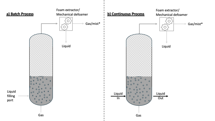
Figure 18-4. Diagram comparing batch (a) and continuous (b) foam fractionation processes. (*) Gas/mist may require monitoring or additional treatment for VOCs or PFAS.
Source: Drawing by Dr. Pradeep R Shukla, Aquarise Innovations.
Batch and semibatch foam fractionation takes place in a vessel that is filled with the water to be treated. Gas is introduced in the bottom for the duration of the treatment batch, and after the foamate is recovered, the treated water is discharged from the vessel (Burns, Stevenson, and Murphy 2021; Malovanyy, Forsén, and Lihammer et al. 2025). Continuous foam fractionation typically uses a vertical column with water flowing countercurrent to the air stream. PFAS are removed by the bubbles into a foamate while the treated water is continually discharged (Smith et al. 2022; McCleaf, Kjellgren, Ahrens 2021). Management of foamate is presented in Section 18.4.3.
Most foam fractionation vendors operate traditional systems requiring the creation of a foam. When the feed-water chemistry lacks sufficient amphiphilic substances such as medium/high PFAS concentrations or other non-PFAS surfactants, the vendor’s foam fractionation solutions typically add several foaming additives (for example, surfactants) to prevent depletion of amphiphilic substance during foam fractionation to maintain foam generation (Buckley et al. 2022; Malovanyy, Forsén, and Lihammer et al. 2025; Klevan et al. 2025). Alternatively, countercurrent operation can be used to increase foamability by transfer of foam generated in a downstream column into the upstream column, increasing the steady state concentration of surface-active species in the initial treatment stages (McCleaf, Kjellgren, and Ahrens 2021). Other commercialized foam fractionation systems have demonstrated effective removal of legacy PFAS without any froth/foam creation where the vendor system operates in either bubble fractionation mode or aerosol fractionation mode (McCleaf, Kjellgren, and Ahrens 2021; Morrison et al. 2023; Nguyen et al. 2024). Application of bubble separation techniques allows high levels of PFAS removal from nonfoaming waters.
For example, if the concentration of PFAS in the water to be treated is high and readily foams, then foam fractionation with normal aeration and vessel fill volumes is typically applied. If the subject water excessively foams, then reduced aeration or mixing various waste streams can be considered to bring the foaming range into the optimal operation range to remove the PFAS from treated water. Either way, the objective is to create a column of aerated water underneath a foaming phase on top. In bubble fractionation, the vessel fill volume is typically higher than with less foaming water. The nature of low-foaming waters prevents bubbly liquid from forming a froth/wet foam or dry foam via interstitial drainage, but higher vessel fill volumes (lower air/water ratios) result in very little frothing but removal of PFAS as bubbly liquid collected from the fractionation vessel (for example, by spilling over the primary fractionation weir). Bubble fractionation typically achieves lower treatment results compared to traditional foam fractionation because bubble fractionation does not provide an opportunity for froth to climb a froth/foam chimney (air gap) to drain interstitial liquid, which may carry residual PFAS, back into the aerated bulk subject water. Bubble fractionation also results in a wetter foamate, resulting in lower volumetric concentration factors. The lower volumetric concentration factor is not necessarily an indicator of PFAS removal but does increase the volume of foamate that needs to be treated or disposed of. The foamate volume generated is variable and depends on the foamability of the water being treated.
PFAS removal mechanisms during foam fractionation vary, and multiple mechanisms may contribute to PFAS removal depending on the water being treated and the specific foam fractionation equipment used. For example, some waters may exhibit significantly reduced bubble formation at the top of the aerated water column when treated in the usual manner. In such cases, aerosol fractionation may be the primary PFAS removal mechanism while bubble fractionation or foam formation may be less important. To enhance aerosol fractionation, vessel fill volume can be set low in a wide-body primary fractionator, reducing aeration and creating smaller bubbles that burst, forming aerosol fragments for condensing back into a liquid foamate. This method has been shown to remove long-chain PFAS if the fractionator can be operated to avoid creating a foam blanket that would capture aerosols before they can be condensed.
18.4.1.5 Pretreatment Considerations
For most waste streams, foam fractionation can be operated with little or no pretreatment and used as a stand-alone PFAS removal technology or incorporated into a treatment train (Burns, Stevenson, and Murphy 2021; Sochacki, Michorczyk, and Vogt 2025). Because there is little pretreatment required, a foam fractionation treatment process can be placed nearly anywhere in a treatment train. Ideally, foam fractionation placement prior to the generation of organic solids would be of great benefit as the separation of PFAS during foam fractionation may limit the amount of PFAS that sorbs onto settleable solids. However, in some circumstances this may be problematic. For example, using foam fractionation to treat raw sanitary sewage may result in the generation of odors, and placement as a tertiary process after secondary treatment may be warranted. If odor is the only concern for the placement of the foam fractionation system, it can be mitigated by the design of off-gas recirculation or treatment as discussed below.
Most co-contaminants or impurities that affect solid phase sorption-based treatments (for example, metals, salts, and organic carbon) do not affect the efficiency of PFAS removal by foam fractionation, and in some cases, may enhance foaming and/or PFAS removal (Buckley et al 2022,; Smith et al. 2023; Wang et al. 2023). However, there are exceptions. The presence of suspended solids in the liquid sometime hinders complete PFAS removal. Suspended solids, especially carbonaceous materials, tend to adsorb PFAS to achieve an equilibrium between the PFAS concentration in the liquid and solid phase. These trapped PFAS are not removed during the foam partitioning and get carried over in the treated liquid (We et al. 2025). Operational strategies, including air injection rate modification and chemical addition, may be used to enhance the capture of suspended solids within the foamate to alleviate this concern. Another exception is measurable oil and grease or NAPL due to interactions between the air-water and NAPL-water interfaces (Brusseau 2021). Where oil and grease are present, an oil-water separator or other pretreatment is recommended prior to foam fractionation to bring the total oil and grease (TOG) concentration below 100 ppm. Dissolved air flotation may also be used for pretreatment to remove oils and grease (Al-Shamrani, James, and Xiao 2002).
Certain pollutants such as benzene, mercury, and other VOCs in the influent liquid will trigger the emissions impact assessment. The air or gases emitted from the treatment process could contain high levels of volatile pollutants due to the partitioning of these pollutants from the liquid phase to gas phase. Hence, a complete assessment of the influent liquid chemistry needs to be undertaken to ensure a proper design of the emissions management process. The foam fractionation process can also generate mist in the exhaust air, which can emit pollutants, including PFAS, into the atmosphere. Effective mist elimination, treatment, or recirculation systems should be evaluated and could include the use of demisting pads, a cyclonic demister system, and/or sorbent beds or canisters.
Although metals are unlikely to impact PFAS removal during foam fractionation, the aeration of water during treatment may affect redox-sensitive metals (for example, iron and manganese), which may precipitate as solids. The buildup of solids from precipitated metals, salts, and carbonates may increase the maintenance of foam fractionation equipment so the cost and benefits of additional pretreatment should be considered.
Foam fractionation aeration rates are not usually sufficient to replace other treatment (for example, air stripping) for the removal of volatile constituents from the aqueous stream, but the potential for these contaminants to be present in air emissions should be considered. Pretreatment or treatment of gaseous emissions can mitigate the release of volatiles.
18.4.1.6 Operational Considerations
During the design and operation of foam fractionation systems, there are numerous factors to consider that may affect PFAS removal and waste generation for a particular water stream. Some factors are applicable when selecting a particular piece of equipment while others can be adjusted during operations. When selecting equipment, there is a tradeoff between flexibility and capital cost that should be considered. Adjustable operating parameters may be proprietary, but they generally include:
- Batch vs. semicontinuous batch vs. continuous flow operation
- If batch or semicontinuous batch, the batch duration
- If continuous or semicontinuous, the flow direction (countercurrent or co-current), effluent location (for example, top, middle, or bottom), and overhead pressure
- Liquid level in the vessel
- Influent and effluent flow rate
- Type of gas used
- Volume of gas, velocity and turbulence of gas, size of the subsequent bubble once introduced to liquid
- Method of removing and handling PFAS concentrate within the system
- Number of active treatment stages in the multistage process with bypass feature
- Co-surfactant chemical feed dosage for enhanced PFAS removal, if used
- Additive chemical feed dosage to increase unit process flow, if used
- Off-gas treatment (if needed)
There is sometimes a tradeoff between concentration/enrichment factor and PFAS removal efficiency: Higher gas flow rates and additive dosing can increase PFAS recovery, but lower enrichment, leading to larger waste volumes (Sochacki, Michorczyk, and Vogt 2025; Comfort et al. 2025; Klevan et al. 2025; Klevan et al. 2025).
When selecting and optimizing a foam fractionation system, it is important to consider the feed water being supplied. If the feed water is seasonal or intermittent, batch or semibatch systems may provide flexibility if sufficient storage is available to equilibrate flow during high flow periods. Generally, these systems are not negatively impacted by downtime and can be restarted when feed water is available. As with any water treatment equipment, certain parts (for example, pumps, valves, and seals) should be regularly exercised or maintained during prolonged shutdowns.
When starting a foam fractionation system, there is typically a period of optimization during which there may be inconsistencies in treatment and, potentially, lower PFAS removal (Burns, Stevenson, and Murphy 2021; Malovanyy, Forsén, and Lihammer et al. 2025). Depending on the purpose of treatment and the requirements for discharge/use, it may be necessary to temporarily store treated water during optimization. This water can then be reprocessed after the system has been optimized and its capability to meet discharge requirements has been documented.
Like all water treatment equipment, foam fractionation systems require periodic cleaning and maintenance and may need to be fully drained for long-term storage or relocation. These activities may require storage and disposal of PFAS-impacted waters if there is not available alternative treatment on-site. If the shutdown is temporary, these waters may be stored and processed through foam fractionation when the system is restarted.
Seasonal variations in air and water temperatures are unlikely to affect foam fractionation performance. We et al. (2024) found no significant impact of temperature on long-chain PFAS removal, although there may be a slight improvement in short-chain PFAS removal at lower temperatures, but there have been limited studies on this subject.
18.4.1.7 Air Emissions
Releases of PFAS to the atmosphere from the foam fractionation process through volatilization or aerosolization are a concern but may be controlled. Volatile PFAS can be stripped from water and transferred to the vapor phase. Most PFAS of interest have low volatility, so minimal volatilization is expected. Vapor phase controls (for example, vapor-phase GAC) can be included to reduce emissions. Other volatiles (for example, VOCs) can also be stripped during foam fractionation and may require additional vapor phase controls. PFAS in air emissions can also be adsorbed to particulates or entrained in aerosols (Smith et al. 2023; Lee and Venkatesan 2024; Nguyen et al. 2024). These can be mitigated by the design of the system or additional controls such as filters, moisture traps, or knockout pots with consideration for humid fractionation reactor conditions. Additional information regarding air treatment methods can be found in Section 12.5 . Some systems have been configured so gases from fractionation vessels are reintroduced into the system. This could lead to the buildup of volatiles in the system if they are present in the water to be treated. The use of monitoring and controls to mitigate any associated risks may be needed. Some systems have been configured so gases from fractionation vessels are reintroduced into the system. This could lead to the buildup of volatiles in the system if they are present in the water to be treated. The use of monitoring and controls to mitigate any associated risks may be needed.
Long-chain PFAS (for example, PFOS, PFOA, PFHxS) can also be generated as aerosols, where small micro/nano bubbles (including macro bubbles) are allowed to burst at the top of the bulk aerated foam fractionation column in the absence of any froth/foam blanket or other mechanical/physical blanket, which would serve to entrap such aerosols (Lee and Venkatesan 2024; Nguyen et al. 2024).
Air toxics regulations and analytical methods should be evaluated and considered. The ITRC PFAS Air Criteria Table (PFAS Environmental Media Values Table Excel File) can be referred to for applicable standards and guidance values for PFAS in air.
In the United States in August 2024, New Jersey, New Mexico, and North Carolina petitioned the USEPA to designate PFOS, PFOA, PFNA, and HFPO-DA (GenX) as hazardous air pollutants, to be regulated under Section 112 of the Clean Air Act.
Section 11.1.7.12 provides sampling procedures for air emissions to air and ambient air, and Section 11.2 provides additional information regarding USEPA Other Test Method 45 (OTM-45), Measurement of Selected Per- and Polyfluorinated Alkyl Substances from Stationary Sources, Revision 1 (USEPA 2024), and Other Test Method 50 (OTM-50), Sampling and Analysis of Volatile Fluorinated Compounds from Stationary Sources (USEPA 2024). These could become a future cost driver or consideration as USEPA is increasing testing and developing new methods. For smaller emissions sources, such as the currently available foam fractionation systems, the sample collection protocols in OTM-45 may not be practical or cost-effective. Alternative, non-isokinetic sampling methods, such as those based on USEPA Method TO-13A (USEPA 1999), have been independently developed for some applications.
18.4.2 Performance Evaluation
Because PFAS adsorption mechanisms may vary for different water types and foam fractionation equipment, bench and pilot testing are recommended to assess potential performance and optimal operating parameters, which may include:
- The performance of different gas types (air, ozone, nitrogen)
- Bubble sizing
- Air flow rates
- Batch treatment times or hydraulic residence times
- The use and dosage of co-foaming additive(s)
Table 18-5 and subsequent sections describe some of the performance testing that can be completed to aid in the selection and design of foam fractionation systems. When evaluating foam fractionation, practitioners should consider these key questions and their purpose:
- Is the liquid material to be treated listed as “applicable” or “non-applicable” in Section 18.4? This will help set the expectations for the potential to remove PFAS and determine treatment objectives; greater PFAS removal would be expected in applicable liquids.
- Is there excessive foaming, insufficient foaming, or lack of bubble formation of site water upon conducting lab bench-scale feasibility testing? The foaming characteristics of the water will help determine the predominant PFAS removal mechanisms and corresponding foam fractionation equipment selection and operating settings. They can also determine the need for foam management/suppression systems or indicate the need for non-PFAS-containing foaming additives to enhance PFAS removal.
- Is there a site history of anti-foaming agent usage (for example, to wastewater or leachate) or use of foam application to manage offensive odors (for example, landfill odor management)? This information will help clarify the expected quality and quantity of foam formed and the considerations in item 2 above (for example, anti-foaming agent presence in the liquid may hinder effective foaming rates, and conversely, the same may be true where foaming agents were used for odor or mist suppression.
- How stable is the foam (for example, what is the foam collapse rate, such as millimeters of foam height drop over 2 minutes, measured during lab bench-scale feasibility testing, or the concentration of methylene blue–active substances in the liquid)? This can be used to determine whether the foam is stable or transient and can affect how foamate is managed after foam fractionation.
- What is the optimal liquid height in the foam fractionation column? This will affect PFAS removal rates and overall system throughput.
- What is the optimal aeration rate and pattern? The pattern of aeration and overall aeration rate can affect PFAS removal rates and the overall quantity of foamate generated. By tuning the system to optimal aeration rates and patterns, including pulsing or stepwise approaches, the PFAS removal rates may be optimized.
- Should we use aerosol, bubble, or foam fractionation setup? The setup will affect the operating parameters (for example, fill height, aeration rate, foam collection method) that will yield the optimal PFAS removal rate.
- Which foamate removal system should be applied (for example, weir or vacuum)? The foamate removal configuration can affect both PFAS removal rates and waste volume produced.
- If short chains need removal, which foam booster of co-surfactant addition should be used, how much, and do these foam boosters transfer into foamate (waste) with PFAS or remain in treated water for recycling in a soil washing batch process? Foaming additives can add cost and complexity to systems and may have their own toxicity that should be considered and balanced against enhanced PFAS removal. Additional discharge permitting considerations should be weighed before deploying field-scale systems.
- Is the addition of salt needed? High salt concentrations may improve foam fractionation performance, but the benefit must be considered against the additional cost, complexity, and maintenance.
- What impact does altitude or environmental conditions, such as liquid temperatures, air temperatures, and humidity, have on stripping and enrichment performance? Although there is little evidence that these factors affect foam fractionation performance, difference between bench/pilot test conditions and field conditions should be considered when interpreting data.
- If hard water is to be treated, how should it be managed (for example, pre-aeration plus filtration plus auto acid dosing to control pH post–foam fractionation at 6.8–7.6, anti-scaling chemical) to prevent post-foam fractionation scaling and fouling polishing systems and/or aquifer reinjection? Scaling in water treatment equipment can increase maintenance costs and downtime. The potential for scale formation and solids precipitation should be considered and weighed against the cost of additional pretreatment.
- If co-contaminants are present in the liquid, how might they affect system fouling or performance, either positively or negatively? Knowing the co-contaminant removal potential, such as organics that may increase cleaning frequency or volatile co-contaminants that may necessitate more frequent vapor treatment change-outs, may benefit the overall decision to deploy foam fractionation.
Additional site-specific considerations for foam fractionation include availability of suitable power, location of influent connections, location and type of discharge, location of safe temporary storage of concentrated PFAS waste, and the need for a level surface that can withstand the heavy loads of the treatment equipment (hardstand).
Table 18-5. Summary of performance test options for evaluating foam fractionation
| Test Type | Relative Time to Completion | Relative Cost | Ability to Assess PFAS Removal? | Predictability of Full-Scale Performance |
|---|---|---|---|---|
| Shake and Foamability Tests | Shortest | Least | No | Poor |
| Modeling | Short | Low | Maybe | Low1 |
| Bench-scale Testing | Moderate-low | Moderate-low | Yes | Moderate2 |
| Pilot | Moderate-high | Moderate-high | Yes | High2 |
| Full-scale Demonstration | Longest | Highest | Yes | Best |
1 Current models are mostly empirical and are based on past performance. Limited data are available on comparisons among model, pilot, and full-scale foam fractionation systems.
2 The size and scale of bench- and pilot-test equipment is typically smaller than the full-scale equipment and may provide only an approximation to full-scale operations. The nature and magnitude of uncertainties should be determined in conversations with vendors or consultants and included in interpretation of results.
18.4.2.1 Shake and Foamability Tests
Although not scientifically rigorous, simple shake tests may be used in screening tests to assess whether a specific water will generate foam without the addition of foaming agent (note: the presence/volume of foam created is not necessarily indicative of PFAS removal by foam fractionation). To obtain measurable results, a foamability test is recommended, in which a standard column 0.5 meter in height and 10 centimeters in diameter is used for generating foam in the liquid and the rates of foam formation and collapse are measured.
18.4.2.2 Bench-scale Testing
Bench-scale units can be used to treat a small volume of water using foam fractionation to assess potential PFAS removal rates, the quantity of foamate generated, and concentration factors. Bench-scale tests typically generate insufficient foamate volumes to test additional concentration or destruction steps, so field pilot testing is often used. Removal rates at bench scale may differ from those in full-scale optimized foam fractionation systems due to the limited volumes available for optimization. Aeration rates, fill volumes, treatment times, and surfactant addition (type, dose, rate) can all be tested during bench or field pilot tests. Descriptions of bench-scale testing are provided in several published articles (Buckley et al. 2023; Buckley et al. 2023; Buckley et al. 2022).
18.4.2.3 Field Pilot Testing
Field pilot testing is the recommended way to assess the suitability of foam fractionation for a particular water (Klevan et al. 2025). A foam fractionation pilot test plan should include similar considerations to adsorptive media pilot test plans described in Section 18.3.2.5. Foam fractionation pilot tests can be completed using full-scale equipment or smaller equipment designed specifically for pilot testing (Burns et al. 2022; Smith et al. 2022). Although smaller equipment may decrease the costs of pilot testing, there may be some uncertainty in directly translating results to larger, scaled-up systems. One significant advantage of pilot testing is the ability to test multiple fractionation conditions over the course of the test, including different treatment times, fill volumes, aeration rates, and additive doses, without being limited by the volume of water available in a bench-scale test. The duration of the pilot test can be longer or shorter depending on the conditions to be tested, site-specific objectives, and variability of the source water. Influent and effluent samples are typically collected for each test condition to assess performance. In addition to analyzing samples for PFAS concentration, it may be useful to measure additional parameters such as metals (to assess changes due to oxidation), foaming additives (to measure removal), VOCs (to assess removal), and other parameters that may be useful for a particular application. Emissions control and testing may also be necessary to evaluate evolution of vapors (PFAS or other co-contaminants).
Pilot testing also provides an opportunity to evaluate integration of foam fractionation with existing infrastructure and as part of a treatment train and may be combined with testing additional PFAS removal technologies, such as downstream adsorptive media. Pilot tests should be performed with sufficient duration and treatment volumes to generate a representative volume of PFAS concentrate. Depending on the number of fractionation steps performed, a large volume of water may need to be treated to generate sufficient foamate for evaluation. The volume of final foamate generated can be compared with the volume of water treated to determine a concentration factor, which is useful for full-scale planning and estimating long-term operations and maintenance costs. Larger scale pilot testing can also be useful to generate sufficient foamate to test and evaluate destruction and disposal technologies.
18.4.2.4 Modeling
Laboratory, bench, and pilot testing are currently the best tools to predict performance. Pilot testing is typically the most accurate method for optimizing the design of a foam fractionation system, but has higher costs, especially when scaling up or evaluating multiple process parameters or system configurations. Ideally, process modeling could offer a cost-effective means to use testing data to optimize process parameters and down-select system configurations, reducing the need for extensive experimental trials. However, due to the complex and chaotic nature of the process, there are no known mechanistic models that can generally predict performance across fractionation applications. For instance, researchers have recently developed mechanistic models of varying complexity for protein enrichment applications (Keshavarzi et al. 2022; Grassia 2023), but so far, no similar model has been translated into a tool used by practitioners in the environmental remediation field. Several scientific publications have investigated the adsorption models and associated parameters for PFAS on bubbles and aerosols (Buckley et al. 2023; Schaefer et al. 2019; Brusseau and Van Glubt 2019; Brusseau and Van Glubt 2021; Sha et al. 2021; Wang et al. 2023), but to date, none of these efforts has been incorporated into publicly available process models for PFAS removal from water. Foam fractionation providers have developed empirical models that can be used to estimate removal of specific PFAS. The performance of these models has not been independently verified, but additional work is ongoing to gather performance data to improve predictive performance based on influent water chemistry. As foam fractionation evolves, further data are collected, and a greater understanding of water chemistry effects is obtained, algorithms may be improved, or empirical models developed.
18.4.3 Fate of PFAS-containing Foams
The objective of foam fractionation is to concentrate large volumes of water with dilute PFAS concentrations into small volumes with high PFAS concentration. Separated foam, bubbles, or aerosols from the initial fractionation stage can be processed through additional stages to provide further volume reduction and increasing PFAS concentration. Depending on the liquid matrix type (for example, groundwater, landfill leachate), volumetric concentration factors of 10 times to 1,000,000 times have been achieved, such that the processing of 1,000,000 gallons of influent results in the generation of 1 gallon of foam concentrate or foamate as the foam eventually condenses back to an aqueous solution (Burns, Stevenson and Murphy 2021; Smith et al. 2022; Wang et al. 2023). The volumetric concentration factor is unique for each water and foam fractionation process and cannot be easily predicted without bench and/or pilot testing. This foamate is then more economical and efficient for consideration to be processed by various field-implemented or emerging destructive treatment technologies or disposal methods, including, but not limited to, those listed below. When considering the economics of destruction and disposal, it is important to consider trade-offs between volumetric concentration, PFAS removal, and system throughput.
- Sorption and Stabilization/Solidification (Section 12.7.1)
- Supercritical Water Oxidation (SCWO) (Section 12.6.3.12 and Section 1.6.2)
- Alkaline Hydrothermal Reaction (Section 12.6.5)
- Electrochemical Treatment (Section 12.6.3.6)
- Plasma Technology (Section 12.6.3.8)
- Photolysis/Photochemical Oxidation (Section 12.6.3.5)
- Incineration (Section 12.4)
- Deep Well Injection (Section 12.6.6)
18.5 Resources for Decision-Making
Many factors should be considered when identifying a PFAS solution, including the treatment objectives and site-specific factors discussed in Section 18.2. Competing cost drivers, environmental impacts, and life cycle sustainability considerations (Section 12.9) also factor into these decisions. Several resources are available to develop preliminary cost estimates.
USEPA has published example applications of their own cost models of PFAS treatment of drinking water for GAC, IX, and membrane systems (USEPA 2023). Although capital costs for adsorption-based technologies are somewhat transferable across applications, O&M costs will heavily depend on project specifics, including influent water quality, influent PFAS types and concentrations, and targeted effluent PFAS types and concentrations. Costs may also vary significantly based on the degree of pretreatment required prior to adsorptive treatment. A study commissioned by the Minnesota Pollution Control Agency (MPCA) provided cost curves for treating liquid waste streams using multiple adsorptive technology configurations, including GAC, IX, RO with GAC+IX treatment of concentrate, and foam fractionation (Barr Engineering Co. & Hazen and Sawyer 2023). In the MPCA study, pretreatment of wastewater effluent prior to adsorption accounted for one-third to one-half of 20-year costs, depending on facility size and characteristics. All costs presented included high-temperature incineration of treatment residuals. Cost curves included wastewater effluent for facilities treating between 0.1 million gallons per day (MGD) and 10 MGD and landfill leachate and compost contact water for facilities managing between 1 gpm and 100 gpm (Barr Engineering Co. & Hazen and Sawyer 2023). The costs developed for aqueous solutions were associated with individual treatment targets (objectives) to reduce concentrations to 5 ng/L each for PFOS, PFOA, PFHxA, PFBS, PFBA, and 6:2 FTS, with N-EtFOSAA included only for landfill leachate. Most notable were the targets of 5 ng/L associated with short-chain PFAS (PFBS and PFBA). For municipal wastewater treatment plant effluent, the cost study generally estimated 10,000 bed volumes treated before change-out using GAC, and 20,000 bed volumes using IX resins, with a 67% removal rate for each of PFBS and PFBA.
Consideration of social and environmental externalities may also drive decision-making for adsorption-based technology adoption. These can be positive externalities such as reduction in health impacts or improved community resources or negative externalities such as greenhouse gas emissions, ecotoxicity, or degradation of community resources. Social impacts may be difficult to quantify, but planners should engage with community stakeholders early in the project to align interests and communicate project goals. The USEPA (2024) has developed the Clean Water Act Financial Capability Assessment Guidance as a tool that can be used to consider economic impacts to a community and its capability to implement controls such as sorption-based PFAS treatment to meet PFAS treatment objectives. Environmental impacts can be evaluated using several different approaches. LCA tools have been used to compare environmental impacts of single-use media use versus IX regeneration and GAC reactivation (Boyer et al. 2021; Ellis et al. 2023). LCA considers ongoing use of chemicals, water, and energy across use, treatment, and residuals disposal and can be estimated using simple calculation-based models or more complex software such as OpenLCA or SimaPro. The USEPA provides a broader list of tools for environmental impact assessment applicable to remediation projects, many of which can be adapted to water treatment projects (CLU-IN n.d.). Additional sustainability evaluation resources are also available through USEPA (USEPA 2025).
An example decision matrix for assessment of GAC, IX resins (usually anion exchange resins), and foam fractionation can be found in Table 18-6. The example decision matrix compares three different adsorption treatments and provides an evaluation based on several decision-making criteria. For this example, all three treatments are assumed to be able to meet treatment goals. However, each treatment has different advantages and disadvantages depending on site-specific factors. General pros include (1) GAC generally has lower unit costs than IX resin, (2) IX may have a smaller footprint and higher mass loadings, and (3) foam fractionation has a high concentration factor and low pretreatment. This example table provides a comprehensive comparison of these three treatments based on various criteria to help in the decision-making process. Some states have also published decision-making tools for PFAS treatment selection. For instance, Arizona has published a set of decision trees to aid in selection between GAC, IX, and high-pressure membranes for PFAS treatment in drinking water (AZ DEQ 2024). This example matrix helps evaluate options and make informed choices by comparing them against specific criteria (effectiveness under varying conditions, capital and operational expenses, and other factors). Judgments in this table were derived from information presented in the PFAS-1 Document (https://pfas-1.itrcweb.org) and available literature (Burns, Stevenson, and Murphy 2021; DiGuiseppi et al. 2024; Ellis et al. 2022; Grieco et al. 2021; Liu and Sun 2021; Murray et al. 2021; Murray et al. 2023; USEPA 2024; We et al. 2024). This decision matrix table is provided as an example. Actual selection of technologies may vary depending on site-specific conditions.
Table 18-6. Example decision matrix comparing foam fractionation, GAC, and IX resin
| Adsorption Treatment | Foam Fractionation1 (FF) | Granular Activated Carbon (GAC) |
IX Resin (IX) |
|---|---|---|---|
| Decision-Making Criteria | |||
| Ability to Treat High Concentration (>1 ppm) PFAS Influent | Up to ~10 ppm limit, depends on mix of PFAS | Limited by size/cost | Limited by size/cost |
| Treatment of Short-Chains (<6C) | Low removal without foaming additives | Typically low efficiency but depends on specific PFAS and design EBCT | Moderate to slightly more efficient than GAC |
| End Waste Product Mass/Volume | Liquid PFAS waste 500–1,000,000x
Volumetric concentration factor |
ug/g to mg/g sorptive capacities possible, ~85% sorbent reuse with reactivation | ug/g to mg/g sorptive capacities possible; regeneration and reuse are possible but may not be economical |
| TOC, Ion, Metal Interference | Little to none | TOC competes for adsorption site and reduces PFAS adsorption capacity, increases of 0.1 to 1 mg/L can drop the bed volumes to breakthrough by an order of magnitude. Precipitation and clogging can increase backwashing frequency | Ions and organic acids can outcompete PFAS for exchange sites on the beads |
| Solids | Above 2% requires filtration | Suspended solids may clog access to surface area, requiring backwashing and potentially reduced adsorption capacity when fouled | Similar solids concern to GAC |
| Pretreatment Requirement | Oily water, very high solids | Oily water, solids, high TOC, high Fe/Mn | Oily water, solids, high TOC, salinity, and other anions |
| Capital Expenditure2 | Medium | Low to medium, depends on pretreatment requirements | Low to medium, depends on pretreatment requirements |
| Operational Expenditure2 | Low, generally less reoccurring costs than sorbents due to lack of media. Concentrate disposal is a consideration. Higher electric demand for low concentrations. | Medium, reoccurring cost of GAC and reactivation or disposal | Higher unit cost of sorbent than GAC |
| General Pros | High concentration factor/low pretreatment. Small liquid waste volumes. No sorptive media. | Reactivation possibility, generally stakeholder acceptable, generally lower unit cost than resin | May be a smaller footprint. Potentially for higher mass loadings and selectivity |
| General Cons | Most applicable to long chains/new developments still occurring. Limited throughput in current commercially available systems (<500 gpm). Not typically effective at low concentrations | Complex geochemistry interferes with PFAS removal. Perpetual change-outs and often more frequent than piloted change-outs | Higher unit cost of the sorbent, perpetual change-outs though frequency may be lower than with GAC |
1 Note that though this example decision matrix table evaluates technologies individually, foam fractionation can be combined with GAC/IX resin depending on site-specific concentrations and conditions.
2 Capital and operational expenditures can vary depending on vendor-specific equipment.
When evaluating water containing PFAS to be treated, understanding the basic pros, cons, and limitations of available treatment technologies can assist decision-making. However, different states, counties, and industries are starting to create their own PFAS guidelines and, as a widespread emerging class of contaminants, PFAS and PFAS technologies are rapidly evolving. These challenges are discussed in greater detail in Section 18.6.
18.6 Barriers, Challenges, and Outlook
Although adsorption-based technologies have proven successful at treating PFAS-impacted water in an array of applications and situations, and the state of knowledge and practice has matured significantly in recent years, practitioners and decision makers may still face challenges and barriers when selecting or implementing these technologies. Performance problems associated with poorly adsorbing PFAS or especially challenging matrixes have already been discussed in previous sections. Therefore, this section will instead focus on regulatory issues, knowledge gaps, and practical resource limitations.
The quickly evolving discovery and research regarding PFAS toxicology and impacts to human health and the environment, and the development and improvement of PFAS analytical techniques, will continue to drive regulatory changes that impact treatment objectives or the transport and disposal of treatment residuals. Although uncertainty exists, the potential for these changes should be considered in evaluating and selecting a PFAS treatment process because the expected lifespan of the treatment equipment may span multiple decades. Consider to what extent PFAS separation can be achieved by the proposed treatment. Consider whether treatment can be expanded in the future or whether other treatment(s) could be added to the treatment train expansion to meet future requirements. Consider the potential for other PFAS to become regulated or for existing PFAS regulatory standards to become more stringent. Depending on locality and application, practitioners and decision makers may encounter overlapping regulations, permitting requirements, and guidance. However, difficulties in this area will likely abate as rules and regulations are finalized and practitioners gain more familiarity with them as the number of full-scale treatment systems in operation increases.
Financial challenges, difficulty purchasing equipment, and lack of operator/maintenance availability can be particularly difficult for small drinking water systems or utilities in remote locations. The USEPA (2024) Small and Rural Systems Fact Sheet summarizes resources available for implementation, funding, and technical assistance to help utilities face these challenges.
Supply chain issues may lead to shortages of media and equipment due to dramatically increased demand. Also, capacity of related services such as analytical laboratory capacity for PFAS may be limiting. However, both issues are likely temporary and will lessen as manufacturers and labs expand operations to meet the increased demands. In addition to the laboratory capacity issues already noted, the lack of rapid, on-site quantitation techniques can present challenges for some applications. Also, quantification of PFAS in challenging matrices, such as waters containing high levels of non-target PFAS, can make quantitation of target PFAS challenging. Advances in techniques or technology may be needed to fully address these challenges.
Utilities, especially potable water utilities, may face challenges with communication issues regarding treatment decisions. For instance, customers may have questions about health risks or why only some PFAS are being treated. This challenge and some strategies for addressing it are discussed in more detail in Section 14. Furthermore, these issues are not necessarily unique to PFAS, and many utilities already confront similar issues for other water contaminants, such as disinfection byproducts. Utilities and remediation specialists are encouraged to work with state, tribal, and federal partners to develop communication plans to address these issues.
Performance modeling for adsorptive processes, which can be used to maximize utility of testing data and inform cost analysis, faces several challenges. Very few open-source, transparent models are available. USEPA has open-source tools for modeling GAC and IX columns, but parameters for only a few IX resins are published and the effects of background organic matter are difficult to model. A large contributor to these challenges has been the lack of useful laboratory and field data collected with modeling specifically in mind. It can be reasonably expected that additional laboratory studies and increasing availability of pilot data will enable further performance model development.
Along with performance modeling development, wider adoption of lab-scale test procedures such as RSSCTs could potentially increase productivity or reduce the cost of pilot testing and permitting. However, several knowledge gaps remain in this area, and protocols and practice are not yet standardized, especially for IX resins. There are still some basic questions about mechanisms of adsorption of PFAS on GAC and IX resins and the effects of grinding on IX resins that, if answered, would provide additional confidence in conclusions and predictions developed using RSSCTs and other lab-scale tests.
When designing and implementing treatment systems, practitioners often fall back on internal institutional knowledge or standards and design documents that were not designed for the challenges and unique behaviors of PFAS. As such, there is an important opportunity for development of consensus and industry standards of practice to reduce time and cost of designing, reviewing, and optimizing treatment systems.
Current foam fractionation methods can effectively remove long-chain PFAS, including most USEPA-regulated compounds, but struggle with shorter chain PFAS, including PFBS, which is also USEPA-regulated in drinking water. Cationic and non-ionic surfactants have shown promise in removing short-chain PFAS, including PFBS. However, the use of these additives faces challenges with approval and permitting due to knowledge gaps. For instance, analytical methods and detection limits for measuring additive discharge (especially if additives are proprietary) make studying them challenging. Additional research efforts, including toxicity and biodegradation studies, are likely needed before processes using these additives see wide adoption. Scale up of foam fractionation may also be a barrier for some applications. Current commercially available foam fractionation systems typically have flow rate limitations. Although they can be scaled by installing additional treatment units in parallel, this may reach a point of diminishing returns. Research and testing of larger scale foam fractionation systems, capable of treating millions of gallons per day, are ongoing but have not been demonstrated commercially.
Although many barriers and challenges have been discussed here, there is cause for optimism. In general, most of these challenges are expected to lessen as regulatory rules are finalized, regulators and practitioners reach consensus on best practices, and standards are established. Future advances in research and technology of novel sorbents, sorbent regeneration, and PFAS destruction technologies will bring more options for adsorbent and process selection and will potentially make adsorption-based technologies viable for a wider range of waters and site conditions.
Published January 2026.

