12 Treatment Technologies
Treatment technologies for PFAS in environmental media are still evolving and it is prudent to use caution in implementing long-term remedies. Selection of remedial actions should prioritize protection of drinking water sources and human health, with consideration of other objectives (such as reducing risk to ecological receptors and environmental resources, liability, source area mass, mass flux, generation of PFAAs from precursors). At some sites, it might be reasonable to take short-term site actions that address impacted or threatened receptors with the intent of applying more robust and cost-effective technologies as these are developed.
The treatment technologies described in this section are organized into three categories by degree of development and implementation: field-implemented technologies, limited application technologies, and developing technologies. The criteria for each category are further described below.
In the sections below there are boxes with lists of SERDP, ESTCP, and/or Water Research Foundation (WRF), projects for PFAS Treatment Technologies. Due to the volume of information, these boxes are no longer being updated. Current links and information about SERDP/ESTCP projects for PFAS Treatment Technologies can be found at https://serdp-estcp.mil/ and Water Research Foundation projects at https://www.waterrf.org/.
12.1 Overview
Treatment technologies exploit a contaminant’s chemical and physical properties to immobilize, separate and concentrate, or destroy the contaminant. The physical and chemical properties of PFAS make many treatment technologies ineffective, including those that rely on contaminant volatilization (for example, air stripping, soil vapor extraction) or bioremediation (for example, biosparging, biostimulation, bioaugmentation). Even technologies such as thermal treatment and chemical oxidation may not be completely effective at treating PFAS, and multiple treatment technologies may be needed for each treatment scenario to address the mixture of different PFAS that may be present.
Treatment technologies can be employed either ex situ or in situ. For example, when groundwater is extracted via pumping from wells and treated, this would be considered an ex situ approach. In contrast, when treatment materials are injected into the subsurface to separate, destroy, or immobilize contaminants in groundwater under the surface, this would be considered an in situ approach. Many existing treatment technologies have generally been shown to be inadequate; therefore, the unique chemical properties of PFAS often require new technologies or innovative combinations of existing technologies.
A range of technologies exists for treatment of either liquids or solids that may be performed either in situ or ex situ. However, field-implemented technologies for treating PFAS in liquids are mostly limited to ex situ technologies.
Field-implemented full-scale treatment of PFAS-impacted liquids or solids is limited to sequestration technologies that remove or bind PFAS but do not destroy them. Sorption using granular activated carbon (GAC) and ion exchange (IX) media has been proven effective at full scale (see Table 12-1 Treatment Methods Table Excel File). Destruction and mineralization technologies, including bioremediation, chemical oxidation, chemical reduction, and thermal technologies, are being tested. This section discusses treatment technologies for liquids (waters, leachates, or other liquid wastes) and solids (soil, sediment, or other solid wastes).
The treatment technologies described in this section are organized by the degree of development and implementation documented in practice or in peer-reviewed literature, regulatory acceptance, and a consensus process. A consensus for the ranking of each technology is determined by the best professional judgment of members of the ITRC PFAS team after evaluating the current information and considering input from other external parties during regular reviews of the document. The three levels used in this discussion are field-implemented technologies, limited application technologies, and developing technologies.
Although categorized in this way for this document, the state of development and application of treatment technologies is a continuum that is ever-changing and evolving quickly. Technologies may progress through these categories between revisions of this guidance document. Most important is that by categorizing, ITRC neither endorses nor repudiates any technology or its proponents regardless of its state of development. Each technology should be evaluated independently to determine the applicability of the technology for the site conditions and desired treatment objectives. The three categories are:
1) Field-implemented technologies –Technologies that have been demonstrated at multiple sites, under diverse conditions, by multiple practitioners, are commercially available, and are well documented in practice or peer-reviewed literature. Field-implemented technologies have been demonstrated to meet site-specific PFAS treatment objectives, at the intended final application scale, and are widely accepted in the regulatory and scientific community.
2) Limited-application technologies –Technologies that have been implemented on a limited number of sites, by a limited number of practitioners, either at full-scale or field pilot-scale. For this document, full-scale is defined as operation of a fully capable system, intended to entirely address the appropriate aspects of the remedial action objectives (RAOs) for the treated media, and which is not intended to be expanded or supplemented in the future to achieve those final project goals. Field pilot-scale refers to a demonstration project intended to prove the effectiveness of the treatment technology in the field, under site conditions. While these projects may not address the RAOs explicitly or completely, these demonstration projects typically involve continuous operation over months of activity, with robust analytical monitoring, and published results in the peer-reviewed literature. Limited application technologies are supported by a growing body of evidence that they are effective at treating PFAS, but differ from full-scale implemented solutions in that there may not yet be a large body of evidence or broad consensus in the scientific community, including peer-reviewed literature, that the technology meets the criteria for a field-implemented technology. Limited-application technologies for liquids and solids are contained in the Table 12-1 Treatment Methods Table Excel File and discussed in Sections 12.6 and 12.7.
3) Developing technologies –Technologies that have been researched at the laboratory or bench scale. Often, the results from developing technologies are reported by only one group (for example, one university, practitioner, or vendor) or lack detailed independent verification of the treatment effectiveness or mechanisms. Among a wide array of experimental technologies under development, only developing technologies that show promise and have some level of publicly available documentation demonstrating effectiveness are included in this guidance document.
The technology evaluations presented herein provide information on the effectiveness of each treatment technology. This information varies widely among technologies and the data provided are based on the reported test conditions and results. Ultimately, the feasibility of a technology to meet applicable regulatory guidance values and standards often depends on site-specific conditions.
As detailed in Section 8.2.2.4, in the United States, the regulatory standards for PFAS treatment are primarily driven by drinking water mitigation and focused on a small subset of PFAS. PFOS, PFOA, PFBS, and HFPO-DA are the only compounds with federal health advisories (USEPA 2022), and most regulatory discharge criteria for PFAS focus on these compounds. USEPA published a final rule in April 2024 that includes National Primary Drinking Water Regulations (NPDWRs) for six PFAS containing MCL and MCLG values (USEPA 2024). Some states have guidelines, and several have regulatory criteria for additional PFAS not contemplated in USEPA’s April 2024 final rule. The technology evaluation information presented here provides data about PFAS tested for a given technology. This information varies widely among technologies. Additional information on regulations is provided in Section 8 and the PFAS Regulatory Programs Summary Excel File.
12.1.1 Factors Affecting Technology Selection
Selection of a remedy, with confidence that treatment targets can be achieved, depends on several key factors, including the ability to reliably define the nature and extent of contamination, the availability of proven treatment technologies, and the capacity and tools to measure progress and compliance with desired regulatory criteria. A well-prepared conceptual site model (CSM) requires adequate information and is also fundamental to understanding and presenting the rationale and justification for the selected remedy. Additional information on CSMs is provided in Section 2.6, Section 9, and Section 10.
Moreover, proven treatment technologies are limited in capacity and demonstrated ability to meet chosen treatment targets. The comprehensive discussions contained herein reveal many questions and uncertainties that must be addressed.
As an example, factors affecting PFAS remedy selection can include:
- characteristics of PFAS. The wide-ranging chemical and physical characteristics of PFAS affect the treatment effectiveness. Key factors include recalcitrance with respect to common technologies due to the strength of the carbon-fluorine bond, ionic state (anionic, cationic, and zwitterionic), types of ionic groups (sulfonate or carboxylate), lipo- and hydrophobicity, chain length and branching, partitioning coefficients, phase behavior, volatility, solubility, acidity, total PFAS mass, and total concentration.
- changes in PFAS properties. Naturally occurring processes or remedial actions for other (commingled) contaminants, such as chlorinated solvents and petroleum hydrocarbons, can affect PFAS distribution and mobility in groundwater (McGuire et al. 2014). Example changes include:
- The alkyl functional group of some PFAA precursors may be more readily subject to chemical or biological transformation than the fully fluorinated aliphatic chain (PFAAs).
- Partial degradation of the carbon-carbon bonds in the aliphatic chain reported for some chemical remedies generates short-chain PFAS, which may be more mobile (Guelfo and Higgins 2013).
- Modifications in aquifer properties (for example, redox or pH) during remediation of commingled contaminants results in a conversion of some precursors to the more stable and mobile PFCAs (McKenzie et al. 2015; McKenzie et al. 2016).
- co-contaminants, organic matter, and geochemistry. The presence of co-contaminants, total organic carbon, natural organic matter, minerals, and anions can significantly affect remediation. Some technologies that are designed and implemented to treat PFAS co-contaminants may transform perfluoroalkyl acid (PFAA) precursors into more stable perfluorocarboxylic acids (PFCAs) (McKenzie et al. 2015).
- community acceptance. Stakeholders, including community members, are often faced with trade-offs in terms of cost, level of cleanup, and residual contamination as part of remediation efforts.
An additional element of technology selection relates to the optimal conditions under which a specific technology should be considered, as documented in the literature. Not all technologies have been demonstrated as suitable or effective under multiple treatment circumstances. For example, although sorption technologies, such as granular activated carbon or ion exchange media, have been documented in the literature as being both technically effective and generally cost-effective in treating high volume, low concentration liquids, such as drinking water, they are less well suited for low volume, high concentration liquids such as thermal system condensate, ion exchange regeneration fluids, fractionated (for example, reconstituted) foam, or landfill leachate. Conversely, several destructive technologies, such as electrochemical oxidation, nonthermal plasma, hydrothermal alkaline treatment, and supercritical water oxidation, have been shown to be effective for treatment of high concentration, low volume liquids, but may be less suitable for high volume, low concentration liquids. See Section 12.1.4 for considerations for specific environmental media.
For those directly engaged in assessing the suitability of PFAS treatment technologies, a structured process for systematic evaluation is currently under development via a Strategic Environmental Research and Development (SERDP)-funded project (ER18-1633). The project focuses on five lines of evidence to evaluate technology performance and will provide resources to identify relevant information and data gaps and address key questions necessary for that assessment. Additional information is provided in Section 12.9.
12.1.2 Tiered Remedial Approach
Along with the factors affecting technology selection (Section 12.1.1), practitioners should also consider the use of a tiered remedial approach to mitigate the risks posed by PFAS. This may include prioritizing protection of known human receptors from exposure to drinking water contaminated by PFAS by using point of entry (POE) or point of use (POU) treatment systems or connecting residents to public water supplies. Reducing the potential risk to human and/or ecological receptors may require upgrades to wastewater treatment plants; however, large-scale retrofits of wastewater treatment plants for PFAS have not been widely enacted at this time. Once these actions are taken to control risk and exposure, the source(s) of the PFAS contamination can be addressed using the appropriate remedial technology. Cutting off sources and controlling ongoing contaminant flux will influence whether PFAS plumes becoming stable or shrink. Once sources and pathways to receptors are controlled, addressing the pathways of contaminant migration (for example, groundwater plumes, stormwater drainage networks, surface water) becomes the final aspect of the tiered approach. A similar approach for site characterization is described in Section 10.2.
12.1.3 Section Organization
The information presented in the following sections reflects the availability of performance results published, presented, or otherwise publicly available. Section 1.6.6 includes updated technology review papers.
Those technologies that have been implemented in the field at multiple sites, by multiple parties, and have peer-reviewed or practical documentation of performance are discussed in Section 12.2 and Section 12.3. Projects funded by SERDP and the Water Research Foundation (WRF) are also highlighted. This section discusses the following key elements for each of these field-implemented technologies:
- treatment description–background and development of technology
- treatment mechanism–separation, sorption, or destruction
- state of development–applications and degree of commercial availability
- effectiveness–documented treatment effectiveness on PFAS and common co-contaminants along with water quality considerations and pretreatment need and options
- design/operating considerations –critical or unique operational or design needs
- sustainability–footprint, community enhancement, and cost.
Treatment case studies are presented in Section 15.2.
12.1.4 Considerations for Specific Environmental Media
The Priority Topics for Treatment Technologies include considerations for management of PFAS-impacted investigation-derived waste (see Section 1.6.3). Section 1.6.6 includes updated technology review papers.
12.1.4.1 Drinking Water
Public-serving system components are often required to be certified through NSF 61 (https://www.nsf.org), which certifies that they are acceptable for potable water use. Treatment for PFAS in these systems typically uses adsorbents such as GAC (Section 12.2.1.1), IX (Section 12.2.1.2), or RO (Section 12.2.2). Section 18 provides guidance for sorption-based technologies for separation and concentration of PFAS from water.
Remedial actions for PFAS-impacted drinking water from private wells and other nondistributed sources can include providing alternative drinking water supplies, such as bottled water, new nonimpacted source wells or surface water, point of entry (POE) treatment (also referred to as POET), and point of use (POU) treatment. POE treats water as it enters a home or building (for example, immediately after a pressure tank for a private well system) and POU treats water at one or more specific locations (for example, at a kitchen faucet where water is typically directly ingested or used for cooking). POE systems provide “whole supply” treatment while POU provides selected usage point treatment.
NSF International has incorporated PFOA and PFOS into two standards – NSF/ANSI 53 for adsorption systems and NSF/ANSI 58 for reverse osmosis systems – to verify the ability of a water treatment device to reduce PFOA and PFOS to achieve the USEPA health advisory levels of 70 ng/L (NSF 2021; NSF 2019). This method does not evaluate the removal of other PFAS that also may adversely impact water supplies. Systems with this certification are mainly small-scale POU systems such as sink faucet filters, refrigerator water filters, and pour-through filters. It should be recognized that although this certification exists, it is not required. This means that other POU systems as well as POE systems (larger wellhead or large public-serving systems) may not be certified under NSF/ANSI 53 or NSF/ANSI 58 but may be acceptable treatment of PFOA and PFOS.
12.1.4.2 Landfill Leachate
Currently, a majority of landfill leachate is treated for conventional constituents by directly discharging or hauling the leachate to publicly owned treatment works (POTWs). POTWs have been designed to remove these conventional constituents (for example, organics and nutrients), but these treatment systems are not effective at removing PFAS. A relatively small percentage of landfills perform pretreatment to address conventional parameters (for example, BOD, COD, TSS, ammonia-N) prior to discharging to POTWs or perform leachate treatment on-site and discharge the treated effluent under National Pollutant Discharge Elimination System (NPDES) permits. There are currently very few landfills that treat or pretreat leachate specifically to remove PFAS, but this may change as national and state surface water and/or pretreatment regulations are developed.
Wei, Xu, and Zhao (2019) presented a comprehensive review of the state of the science on PFAS treatment technologies for landfill leachate. They noted that various technologies have been widely tested for treating PFAS in drinking water or groundwater, but knowledge is limited on the treatability of PFAS in landfill leachate and the effects of the complex leachate matrix. Leachate contains many competing organic and inorganic constituents, and this complex matrix creates significant challenges when choosing a treatment technology for PFAS removal. Oftentimes, pretreatment of the leachate may be required before applying common PFAS sorption technologies such as GAC or ion exchange resins. If pretreatment is not performed to remove these competing compounds, the sorptive treatment media will foul quickly, which may result in operationally complex and/or expensive systems to treat landfill leachate for PFAS using these traditional technologies. Additional information on integrated remedial solutions is presented in Section 12.8.
Destructive technologies such as plasma, advanced oxidation, reduction, photochemical processes, and sonolysis are largely unproven at present on landfill leachate, and their effectiveness is expected to be reduced when used for treating leachate due to the severe water matrix effect (Wei, Xu, and Zhao 2019). In addition, these technologies have typically not been as effective when scaled up from laboratory studies to the field. Supercritical water oxidation (SCWO) destruction of landfill leachate containing PFAS has been demonstrated but is not well documented in peer-reviewed literature. More information about SCWO is included in Section 12.6.3.12.
Filtration systems such as RO have been proven effective as a separation technology for leachate for a wide range of constituents, including PFAS, but can generate a significant fraction of concentrated residuals that requires management by other disposal/treatment technologies. Foam fractionation shows promise in recent studies for selectively separating large percentages of PFAS from leachate (particularly the longer chain PFAS) while generating manageable fractions of high concentration residuals at a much smaller volume relative to RO reject (Burns et al. 2022; McCleaf, Kjellren, and Ahrens 2021; Robey et al. 2020; Smith et al. 2022).
Overall, further research is needed to develop and demonstrate cost-effective treatments for landfill leachate PFAS removal that are effective at field scale.
12.1.4.3 Biosolids
The Priority Topics for Treatment Technologies include information on treatment of PFAS-contaminated sewage sludge and biosolids (see Section 1.6.5). The Priority Topics for Biosolids Land Application include information about PFAS in biosolids (see Section 1.7).
Biosolids generated by wastewater treatment plants have been historically managed through land application, use or disposal at landfills, or incineration. The regulatory landscape for management of biosolids is evolving, and some states have started to require testing, prohibit land application if concentrations of certain PFAS are greater than specific levels, or have implemented bans on land application. Current regulations and guidance are discussed in Section 8 and in the PFAS Regulatory Programs Summary Excel File.
The fate of PFAS in various thermal treatment processes (for example, incineration, pyrolysis) is an active area of research to better understand the potential formation of byproducts or products of incomplete combustion (USEPA 2024) and is covered in more detail in Section 12.4.
Additional information on biosolids is presented in the ITRC factsheet for Biosolids and Per- and Polyfluoroalkyl Substances (PFAS) (/fact-sheets/) and Section 2.6.4.
12.2 Field-Implemented Liquids Treatment Technologies
These technologies have been implemented in the field by multiple parties at multiple sites and the results have been well-documented in practice or peer-reviewed literature. The liquid treatment technologies in this section may be applied to a variety of PFAS-impacted media, including drinking water (regardless of source), surface water, groundwater, wastewater, stormwater, or landfill leachate. Not all technologies would be appropriate for all applications. Site-specific evaluation is necessary to identify the best technology alternative for a given liquid, system size, treatment goal, and residual media management scenario.
12.2.1 Sorption Technologies
Section 18 provides guidance for sorption-based technologies for separation and concentration of PFAS from water.
Sorption technologies have been used for both ex situ and in situ water treatment applications. Multiple sorption media types may be used in series for ex situ applications to optimize overall concentration reduction and removal capacity. Adsorption and ion exchange (IX) are two “sorption” mechanisms by which PFAS can be removed from water. Adsorption is a physical mass transfer process that uses Van der Waals and/or other weak ionic forces to bind the entire PFAS molecule to the surface areas of the adsorptive media. Ion exchange is the exchange of ions of the same charge. Ion exchange targets and binds to the hydrophilic ionized or functional end of the molecule (for example, the sulfonate in PFOS) while releasing an equivalent amount of an innocuous ion (for example, chloride) into the treated water. This technology is generally considered more applicable to high volume, low concentration liquids than low volume, high concentration liquids.
Several influent water parameters can therefore be expected to impact the sorption efficiency for a specific PFAS. These include pH, ionic strength, the nature and concentrations of organic co-contaminants present (including naturally occurring organic matter [NOM]), competing inorganic ions normally present (for example, sulfate, nitrate, bicarbonate, and chloride), and any suspended solids, potentially precipitating impurities (for example, iron, manganese, calcium carbonate), or biological growth that can foul and degrade the performance of the media. Pretreatment steps may be necessary to optimize the performance of such media, including coagulation, precipitation, filtration, pH adjustment, or oxidant removal. Ion exchange media used for PFAS removal from water use both the adsorption and ion exchange mechanisms. The use of two or more different media in series can be considered if the expected increase in overall removal efficiency can be used to justify the increased equipment cost.
Life cycle cost assessments can be used to compare the long-term cost-performance benefits of various sorption media types. Spent media management can be an important consideration when selecting a treatment technology. Common options for spent media management are off-site disposal by thermal destruction (via commercial incineration or cement kilns), reactivation/regeneration for reuse (which may require management of additional waste streams), and landfilling. Information on specific management considerations for spent media are discussed in the respective sections below.
Incineration and thermal reactivation/regeneration offer the possibility of destruction of PFAS waste streams, though incineration has received recent attention due to possible incomplete combustion and by-product generation and is the topic of current study to better understand the fate of PFAS. Incineration is discussed in Section 12.4.
Related Past, Ongoing, and Recent Research Funded by SERDP (ER) and Water Research Foundation (WRF)
- ER18-1395 Electrically Assisted Sorption and Desorption of PFASs
- ER18-1417 Molecular Design of Effective and Versatile Adsorbents for Ex Situ Treatment of AFFF-Impacted Groundwater
- ER18-1052 Remediation of PFAS Contaminated Groundwater Using Cationic Hydrophobic Polymers as Ultra-High Affinity Sorbents
- ER18-1306 Combined In Situ/Ex Situ Treatment Train for Remediation of Per- and Polyfluoroalkyl Substance (PFAS) Contaminated Groundwater
- ER18-5015 Removal and Destruction of PFAS and Co-contaminants from Groundwater via Groundwater Extraction and Treatment with Ion-Exchange Media, and On-Site Regeneration, Distillation, and Plasma Destruction
- ER18-B3-5053 Evaluation and Life Cycle Comparison of Ex-Situ Treatment Technologies for Poly- and Perfluoroalkyl Substances in Groundwater
- WRF 4913 Investigation of Treatment Alternatives for Short-Chain PFAS
- ER21-1191 Determination of Thermal Degradation Products and Residuals of Per- and Polyfluoroalkyl Substances-Laden Sorbent Materials in Gas and Condensed Phases
- ER21-1238 Sustainable PFAS Treatment Using Layered Double Hydroxide (LDH) Sorbents
- ER20-5182 Validation of Colloidal Activated Carbon for Preventing the Migration of PFAS in Groundwater
- ER18-1026 Rational Design and Implementation of Novel Polymer Adsorbents for Selective Uptake of Per- and Polyfluoroalkyl Substances from Groundwater
- ER20-5252 Anion Exchange Permeable Adsorptive Barriers (PABs) for In Situ PFAS Immobilization and Removal
- ER20-5100 In Situ PFAS Sequestration in AFFF-Impacted Groundwater
- ER21-1185 Thermal Decomposition of PFAS on GAC: Kinetics, Mass Balance, and Reuse of Reactivated Carbon
- ER21-1256 Develop Synergetic Novel Macrocycle-based Sorbents with Thermal Destruction for Enhanced PFAS Removal in Groundwater and Drinking Water Treatment
- ER21-1124 Assessment of Long-Term Effectiveness of Particular Amendments for In Situ Remediation of PFAS in Mixed Plumes
- ER22-3150 Engineering an “All-In-One” Biochar-Surfactant System for Enhanced PFAS Sorption and Reductive Degradation Using a Coupled Ultraviolet and Ultrasonication Approach
- ER22-3155 In Situ Sequestration of PFAS from Impacted Groundwater using Injectable High Affinity Cationic Hydrophobic Polymers
- ER22-3415 Novel Swellable Ionomers for Enhanced PFAS Sorption and Destruction
- ER22-7363 Rapid and Inexpensive Delivery of Particulate Carbon for In Situ PFAS Treatment in Groundwater
- ER22-3119 High-Capacity Sustainable Sorbents for Treatment of PFAS
- ER22-3194 Green Remediation of PFAS in Soil and Water
12.2.1.1 Granular Activated Carbon (GAC)
Treatment Description: GAC is an effective sorbent media for organics that has historically been used to reduce contaminants in a variety of environmental media. The information contained in this section describes ex situ GAC treatment in which water is extracted and transferred from the source of contamination and directed through the treatment system.
Treatment Mechanism: Removal of PFAS by GAC is a physical mass transfer process (refer to Section 12.2.1) from the aqueous phase onto solid media that does not involve or trigger any form of chemical degradation or transformation.
State of Development: The application of GAC as a treatment technology for PFAS removal has been practiced for over 15 years at more than 45 military installations, as well as several industrial sites and publicly owned treatment works (Forrester 2018) involving private and municipal drinking water supplies.
Effectiveness: The following references were used to support the treatability effectiveness discussion presented below for PFAS by GAC: Appleman et al. (2013); Burdick et al. (2016); Cummings (2015); Dickenson (2016); Ochoa-Herrera and Sierra-Alvarez (2008); Szabo (2017); Woodard, Berry, and Newman (2017); Zeng et al. (2020). These references also include more comprehensive bibliographies if further details are needed on specific topics or studies. Literature and supporting column studies have shown that newly placed GAC can reduce effluent concentrations for PFAS listed in USEPA Method 537.1 (Shoemaker and Tettenhorst 2018) to below analytical detection limits until initial breakthrough begins to occur. Because GAC is generally used to treat many common groundwater contaminants, it is capable of also treating most organic co-contaminants that may be present, with the primary impact being increased GAC consumption due to greater loading per unit of time, which may require more frequent change-outs.
Individual PFAS have different GAC loading capacities and corresponding breakthrough times (often defined as the number of bed volumes treated prior to detection in the effluent) (Eschauzier et al. 2012; Zeng et al. 2020). GAC removal capacity for PFOS is greater than PFOA, but both can be effectively removed (McCleaf et al. 2017). In general, shorter chain PFAS have lower GAC loading capacities and faster breakthrough times, but could be effectively treated if change-out frequency is increased. Figure 12-1 provides an example of removal curves and breakthrough information for several PFAS performed at a specific influent concentration based on vendor-supplied column studies.
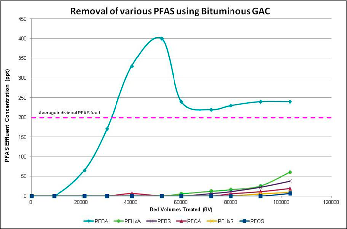 Figure 12-1. Example GAC removal curves at specific influent concentration (15-minute empty bed contact time).
Source: Used with permission from Calgon Carbon Corporation.
More studies are needed to confirm GAC treatment effectiveness for shorter chain PFAS or to identify complementary technologies/materials to supplement GAC removal capability. This may include studying the influence on sorption site competition from PFAS precursors that are often not quantified during the GAC system design. Recent accelerated column tests by vendors have shown the successful removal of a variety of PFAS, including the butyl (C4), pentyl (C5), and hexyl (C6) compounds (Appleman et al. 2013; Dickenson 2016; Brewer 2017; Zeng et al. 2020). Functional groups also impact the ability of GAC to adsorb PFAS. Compounds with sulfonate and sulfonamide groups are more readily adsorbed than those with carboxylates of the same chain length (Appleman et al. 2013; Dickenson 2016; Zeng et al. 2020). Studies in the developmental stage involve the use of other materials that can modify GAC surfaces to improve removal capabilities. Mixtures of powdered activated carbon, kaolinite, and amorphous hydroxide have been tested at the bench- and pilot-scale and have shown high removal rates for shorter chain PFAS in raw AFFF-impacted groundwater (Chiang 2017; Kempisty, Xing, and Racz 2018).
Most of the case studies on full-scale GAC-based systems used to treat PFAS in the literature are based on treatment of PFOA and PFOS in impacted drinking water sources. As such, limited information is available regarding the treatment of other PFAS, or PFAS in other source waters. The full-scale drinking water systems demonstrate that PFOA and PFOS can be removed to below analytical detection limits. More information is contained in the Table 12-1 Treatment Methods Table Excel File. Treatment of groundwater impacted with PFAS from an AFFF release area contaminated with PFAS such as fire training areas (FTAs) may require complex pretreatment and more frequent change-outs (higher influent concentrations compared to influent for drinking water treatment systems) and higher operation and maintenance (O&M) costs.
Design/Operating Considerations: Laboratory treatability tests (for example, rapid small-scale column testing (RSSCT) and accelerated column test (ACT)) are useful for evaluating treatability and determining initial design parameters. Larger scale pilot demonstrations are recommended to establish site-specific design parameters such as adsorption bed depth; GAC consumption rate to meet a given treatment objective; empty bed contact times (EBCTs); projections of breakthrough (based on bed volumes treated); and corresponding change-out frequency/costs. Column studies can also be used to compare loading capacity/breakthrough performance for different types of GAC (for example, different materials, preparation methods, and pore size distributions) offered by various vendors. These studies should always use site water to ensure that the effects of site-specific geochemical characteristics are assessed. Alternative analytical screening methods, for example, total oxidizable precursor (TOP) assay (Section 11.2.2.2), adsorbable organic fluorine (Section 11.2.2.4), and particle-induced gamma ray emission (PIGE) (Section 11.2.2.3), can be used to better estimate potential total mass load during the GAC remedial design phase. Field performance of GAC systems often varies significantly from that predicted in the RSSCT and other bench tests. Proper monitoring is critical to demonstrate that the desired performance is being achieved, especially at system start-up and following media change-out events.
Temporary and permanent GAC systems can be rapidly deployed and require minimal operator attention, if intensive pretreatment is not needed. The GAC media are placed in packed-bed flow-through vessels generally operated in series (lead-lag configuration). EBCTs of 10–20 minutes per vessel are typical (AWWA 2019). PFAS breakthrough is monitored by testing the water, at a minimum, between the lead and lag vessels. Additional sampling ports can be added (for example, at 25%, 50%, and 75% of the depth of the media). When breakthrough exceeds identified change-out criteria, the lead bed is taken offline and the spent GAC is removed and replaced with either new or reactivated GAC. The spent media are disposed off site by thermal destruction or can be thermally reactivated for reuse. Treatment can be continuous if the lag bed is used as the lead bed while the media in the latter are changed out. Figure 12-2 depicts a simple process flow diagram for a GAC treatment system.
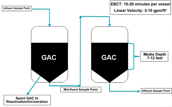 Figure 12-2. Typical GAC treatment system process flow diagram.
Source: Used with permission from Calgon Carbon Corporation.
Various GAC base materials (for example, bituminous coal, lignite coal, coconut shells) can be used for adsorption, though bituminous coal-based GAC has been used for the majority of existing sorption treatment systems for PFAS and current data show that bituminous-based products are more effective for PFAS removal (McNamara et al. 2018; Westreich et al. 2018). Specialized GAC formulations and coconut-based GAC can also be effective. Media selection and life cycle cost will depend upon a number of factors, including PFAS and co-contaminant concentrations, media availability, and pricing.
GAC treatment applications will evolve as analytical methods improve and regulatory concerns encompass an increasing number of PFAS. Shorter chain PFAS exhibit faster breakthrough times (Appleman et al. 2013), so particular attention needs to be given to these compounds if their removal is required. Alternative design optimization approaches or use of other technologies in combination with GAC (for example, ion exchange (IX) resins discussed in Section 12.2.1.2) can address high O&M costs that can be incurred for GAC treatment involving high influent PFAS concentrations, especially if shorter chain PFAS must be removed. As discussed in Section 12.2.1.2, specialty single-use and regenerable IX resins have been developed that have higher loading capacities for shorter chain PFAS. GAC and IX can also be used in series to optimize removal capacity and minimize O&M costs, generally with GAC ahead of IX to remove non-PFAS organics and longer carbon chain PFAS, followed by IX to remove the shorter carbon chain PFAS. This approach has been implemented in the field and is presented in a case study in Section 15.2.2.1.
Spent GAC that contains PFAS can be thermally reactivated and reused, which may result in a lower cost media replacement option versus new GAC. However, some regulatory agencies may not allow the use of reactivated GAC for drinking water systems. NSF/ANSI standards require that the use of reactivated GAC for drinking water systems involve only media generated by the treatment system owner/operator and cannot include a mixture of GAC that originated from other sources. The management of spent media should be planned during the life cycle assessment phase and be documented as the treatment system is executed. Commercial facilities are available for thermal reactivation of spent GAC, which currently are not available for other sorption media and can offer a potential life cycle cost benefit for spent media disposal. Based on vendor feedback (Mimna 2017), commercial thermal GAC reactivation is performed at higher operating temperatures than steam or nitrogen regeneration systems, and may be capable of complete desorption and destruction of PFAS from spent GAC (Watanabe et al. 2016; Yamada et al. 2005). However, similar to incineration, additional studies are needed to investigate the fate of PFAS in the GAC reactivation process.
Sustainability: GAC ex situ PFAS water treatment systems have unique sustainability considerations as well as considerations in common with other ex situ PFAS sorption media water treatment systems (treatment complex construction, utilities, water collection and pumping, and discharge infrastructure). Major sustainability considerations unique to GAC systems are associated with:
- raw material collection and transportation
- GAC manufacturing and transportation
- larger media vessels relative to IX due to longer EBCTs
- larger treatment complex size due to larger vessels
- spent media transportation followed by reactivation, destruction, or disposal.
Multiple resources are available for performing sustainability assessments for sorption remedial designs (Amini et al. 2015; Choe et al. 2013; Choe et al. 2015; Dominguez-Ramos et al. 2014; Favara et al. 2016; Maul et al. 2014; Rahman et al. 2014; Ras and von Blottnitz 2012). Additional information is included in Section 12.9.
Related Past, Ongoing, and Recent Research Funded by SERDP:
- ER21-1185 Thermal Decomposition of Per- and Polyfluoroalkyl Substances on Granular Activated Carbon: Kinetics, Mass Balance, and Reuse of Reactivated Carbon
- ER21-1111 An Investigation of Factors Affecting In Situ PFAS Immobilization by Activated Carbon
- ER20-3034 Thermal Reactivation of Spent GAC from PFAS Remediation Sites
- ER19-5181 Improved Longevity and Selectivity of PFAS Groundwater Treatment Using Sub-Micron Powdered Activated Carbon and Ceramic Membrane Filter System
- ER22-7363 Rapid and Inexpensive Delivery of Particulate Carbon for In Situ PFAS Treatment in Groundwater
12.2.1.2 Ion Exchange Resin
Treatment Description: Ion exchange (IX) resin is an effective sorbent for other contaminants and has historically been used for a variety of water treatment applications (for example, nitrate, perchlorate, arsenic). To date, IX for PFAS removal from water is limited to ex situ applications.
IX resin options for removal of PFAS include single-use and regenerable resins. Single-use anion exchange resins are used until breakthrough occurs at a pre-established threshold and are then removed from the vessel and currently disposed of by high temperature incineration or by landfilling, where permitted. Regenerable resins are used until breakthrough but are then regenerated on site using a regenerant solution capable of returning a reduced capacity to the resin. Temporary and permanent IX systems can be rapidly deployed.
Treatment Mechanism: Removal of PFAS by IX is a physical mass transfer process from the aqueous phase onto solid media that does not involve any form of chemical degradation or transformation. IX resins with positively charged functional groups remove negatively charged PFAS from water by forming ionic bonds (the sulfonic and carboxylic acid heads of PFOS and PFOA are negatively charged at the typical range of pH values found in natural water). Simultaneously, the hydrophobic end of the PFAS structures can adsorb onto the hydrophobic surfaces of the IX resins, leading to increased ion exchange affinity on resins with hydrophobic backbones. Some PFAS at high liquid-phase concentrations (for example, 1 g/L) have been shown to also exhibit nonexchange sorption onto IX resins (Zaggia et al. 2016). However, the specific conditions and underlying mechanisms leading to this nonexchange sorption are not yet fully understood.
State of Development: Ion exchange technology has been used since the late 1930 for common water treatment processes like softening, demineralization, and selective contaminant removal. The development and use of selective resins for PFAS removal is relatively new but already well established. Single-use resins are now widely used for PFAS removal from water due to their simplicity of use and effectiveness in reducing regulated PFAS to nondetect (ND) levels. As of 2019, a limited number of regenerable IX systems have been installed in full-scale applications after successful pilot testing. Collection of data on longer term treatment and on-site regeneration of the IX resin is ongoing at a case study site (Section 15.2.2.2). In general, the removal capacity of the single-use resin is higher than that of regenerable resin, and single-use resin can be more fully exhausted in a lead-lag vessel configuration than regenerable resin. The relative removal efficiency of regenerable and single-use resins depends upon PFAS and co-contaminant influent concentrations and treatment goals.
Effectiveness: Selective IX has been demonstrated to reduce concentrations for a broad suite of PFAS at the bench and field scale for influent concentrations as high as 100s of parts per billion (ppb) total PFAS to below analytical detection limits in effluent (Kothawala et al. 2017; McCleaf et al. 2017; Woodard, Berry, and Newman 2017; Zeng et al. 2020). The affinity of such resin for common subgroups of PFAS generally follows the order PFSA > PFCA. Within each subgroup, affinity increases with increasing carbon chain length, and are not necessarily sequential (that is, longer chain PFCA may be adsorbed better than shorter chain PFSA).
In general, IX resin systems being used for PFAS removal are not installed with the intention of removing co-contaminants. Co-contaminants (including organic and inorganic compounds) may significantly reduce the removal capacity of IX for PFAS, although this depends on the selectivity of the IX resin. Because of the variability in resin behavior, as well as site-specific chemistry and co-contaminants, influent characterization is needed to assess potential pretreatment options to remove co-contaminants. Pretreatment is necessary to prevent fouling (for instance, by iron or manganese) and preserve resin capacity for PFAS removal, particularly in the context of remediation where complex co-contaminant chemistry is expected. Pretreatment needs for drinking water applications may be simpler or not required. Another consideration for drinking water utilities is that, depending on the type of IX resin used, a freshly installed IX column may cause short-term disruptions in pH or corrosivity of effluent water, which may necessitate mitigation strategies such as effluent blending or diverting initial effluent to waste (Smith et al. 2023).
Single-use PFAS-selective IX resins are well-suited to treat low-concentration PFAS such as is typically encountered in potable water treatment systems, where media change-out would be infrequent. Figure 12-3 provides an example of removal curves and breakthrough information for a number of PFAS at the specified influent concentrations (in the legend) based on vendor-supplied data for a full-scale single-use system. Breakthrough is calculated as the ratio of the effluent concentration to the influent concentration (C/C0). It is not uncommon to observe fluctuations in the breakthrough curve in some field pilot studies due to varied influent concentrations over time. For example, after a resin unit is in equilibrium with one PFAS at an initially higher influent concentration, a lower concentration influent can desorb PFAS from the resin, resulting in breakthrough higher than 100%. The typical breakthrough order observed in Figure 12-3 is expected to be similar for various anion exchange resins, as relative ionic bond strengths and carbon chain lengths result in shorter chain PFCAs to longer chain PFCAs desorbing first, followed by shorter chain PFSAs to longer chain PFSAs. Similar responses also apply to GAC.
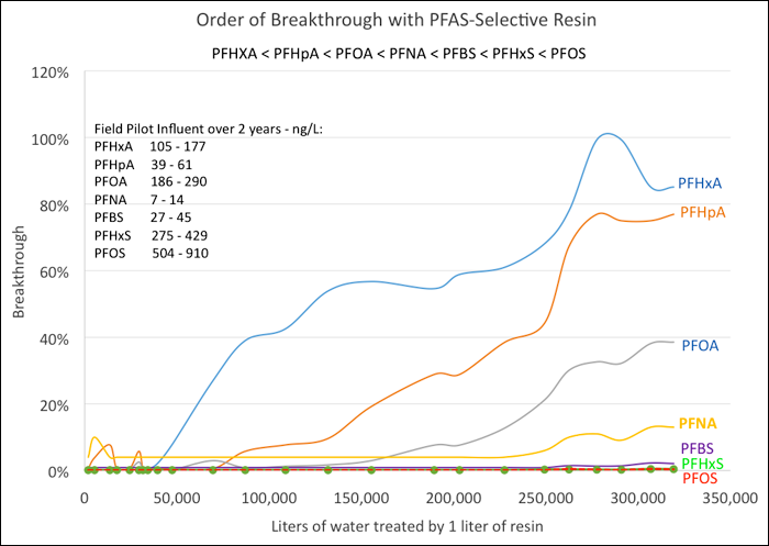 Figure 12-3. Example of IX removal curves from a field pilot study at specific influent concentrations (2.5-minute EBCT). (Note: Initial concentrations in ng/L or ppt.)
Source: Used with permission from Purolite Corporation.
Regenerable IX is not yet approved per NSF 61 for potable water treatment. Regenerable resins are better suited for removal of higher concentration PFAS where the savings realized from reusing the treatment media outweighs the cost of frequent replacement of nonregenerable media. Regenerable IX becomes more efficient than single-pass media when flow rate and concentration increase and RAOs go down, because these factors increase the frequency and volume of media change-outs for single-pass media. These factors also increase the regeneration demand; however, regeneration frequency can be extended by using larger vessels. Cost efficiency and viability of regenerable IX relative to single-use IX and GAC media are evaluated in ESTCP ER18-5015.
An example of typical breakthrough curves for regenerable resin system is shown in Figure 12-4. On the graph the y-axis is sample concentration/original concentration (C/Co), also note the influent PFAS concentrations (in the legend) in Figure 12-4 are higher (reported in ppb) than presented in Figure 12-3 (reported in ppt). Additional details on a regenerable resin system are provided in a case study in Section 15.2.2.2. The cost effectiveness for regenerable resin systems could increase significantly (and thus impact the system’s practical implementability) when a central regeneration facility can be shared amongst multiple PFAS removal systems. The application of single-use versus regenerable resins must be evaluated on a site-specific basis.
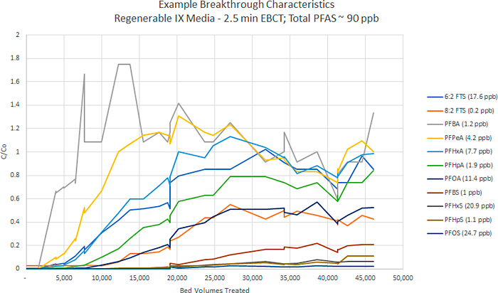 Figure 12-4. Example of regenerable IX removal curves from a field pilot study at specific influent concentrations (2.5-minute EBCT). (Note: Initial concentrations in µg/L or ppb.)
Source: Used with permission from ECT2.
Design/Operating Considerations: IX treatment systems are configured similarly to GAC systems. Refer to Section 12.2.1 for a description of GAC systems that also applies to IX systems, and Section 12.2.1.2 for fouling considerations. Figure 12-5 depicts a simple process flow diagram for a single-use IX treatment system.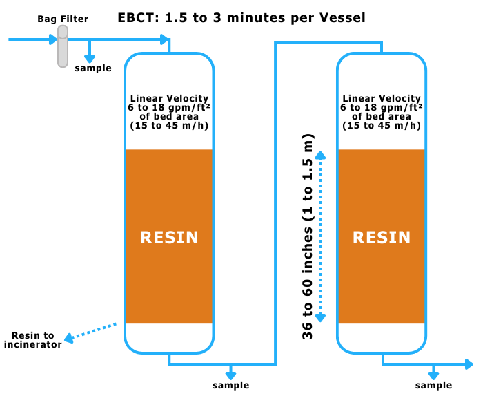
Figure 12-5. Single-use IX process flow diagram.
Source: Used with permission from Purolite Corporation.
Selective IX requires a relatively short EBCT of 1.5–3 minutes per vessel of resin (AWWA 2025), hence smaller resin volumes and smaller, less costly treatment vessels versus GAC, which requires EBCTs of about 10–20 minutes per vessel (AWWA 2019; Brewer 2017) and correspondingly larger volumes of media. Selective IX resins have shown high operating capacities when removing trace levels of PFAS (for example, 100,000–400,000 bed volumes; refer to Figure 12-5), resulting in fewer change-outs of spent IX resin and reduced O&M costs. Capacity depends on the concentrations of competing anions, such as sulfate and nitrate, and on the specific PFAS breakpoint chosen for resin change-out. While lead-lag vessel design is standard, if space allows, it is possible to use a lead-lag-polisher design with three resin vessels in series. The addition of a polisher vessel provides a factor of safety for increasing the loading to the lead vessel, thereby reducing change-out frequency and cost. A lead-lag-polisher design will usually result in reduced operating expenses (OPEX) but higher capital expenses (CAPEX). Therefore, the decision to use it must be done on a case-by-case basis. Pretreatment may mitigate fouling and improve performance.
For drinking water supplies with relatively clean water, the industry is rapidly moving to rely more and more on vendor-provided modeling for common PFAS with such modeling including predicted breakthrough curves and resin capacities for specific PFAS breakpoints. Modeling can evaluate a variety of “what-if” scenarios, such as changing water chemistries and assessing the economics of operating to nondetectable levels or stricter regulatory limits for selected PFAS.
Pretreatment for several influent water parameters has been recommended (Section 12.2.1). Natural organic matter (NOM) is of particular importance because it occurs at concentrations that are three orders of magnitude higher than PFAS. Therefore, NOM can compete for the same ion exchange sites on the resin and can also blanket the surface of the resin beads, thereby blocking access for PFAS to the internal sites on the beads. The negative impact of NOM in groundwater on resin capacity can usually be factored in at the design stage if appropriate data and models are available, because NOM is usually present at less than 2 mg/L. However, when treating surface water with NOM concentrations that can seasonally rise to 5–10 mg/L (and even higher), it is particularly important to consider negative impact on resin capacity. Dixit et al. (2020) evaluated the impact of various dosages of Suwanee River NOM on resin capacity for PFAS and showed decreases of 22%, 50%, and 68% in resin capacity when adding dosages of 5, 10, and 20 mg/L NOM and using an organic scavenger acrylic resin in isotherm test solutions.
Despite the growing adoption of modeling, pilot testing is still recommended when evaluating breakthroughs for multiple PFAS or when the impact of TOC or other contaminants such as iron and manganese must be known to determine pretreatment requirements. In such cases, a technique referred to as accelerated piloting may be used, in which monitoring ports in the pilot column are set at 25%, 50%, and 100% of the resin height. This allows results to be obtained more quickly, but it is with the understanding that the breakthrough profile for each of the ports will be somewhat different. There is also growing interest in using the rapid small-scale column testing (RSSCT) technique for resins. Originally developed for use with GAC, the RSSCT technique uses crushed GAC and shorter EBCTs to quickly predict operating capacity. At this time, it is too early to know if this technique will reliably work for spherical resin beads when crushed.
Selective IX resins show much higher selectivity for PFAS than for common anions in water such as sulfate (SO42-), nitrate (NO3–), chloride (Cl–), and bicarbonate (HCO3–). However, these common anions are generally present in water at about three orders of magnitude higher than PFAS and will be the main competitors for the ion exchange sites on the resin. As such, they will largely determine the operating capacity of such resins. The choice between single-use and regenerable resins will in part be determined by the expected service period before the resin must be either replaced (single-use) or total regeneration costs (including capital and transportation costs). As PFAS concentration increases or as effluent criteria decreases, the frequency of regeneration or media change-out increases. As regeneration or media change-out increases, regenerable IX becomes more long-term cost-effective, if indeed the cost of regeneration is less than the cost of media replacement.
Regenerable IX resin can be reused long term if protected from contact with strong oxidizing agents, foulants, and chemical/mechanical stresses. In recent years, both pilot-scale and full-scale regenerable IX systems have demonstrated long-term durability of the media. One study, ESTCP ER18-5015, demonstrated greater than 95% removal capacity for regenerated media as compared to new media over six loading and regeneration cycles. IX regeneration is a chemical process. Field-demonstrated regeneration uses a solvent-brine solution in which the brine dislodges the ionic head of the PFAS molecule and the solvent desorbs the fluorinated carbon chain (or “tail”) from the IX resin (Woodard, Berry, and Newman 2017; Amec Foster Wheeler 2017). For a regenerable IX system, it is possible to concentrate the regenerant solution and reuse it by distillation (Nickelsen and Woodard 2017). The distillate residue then contains a concentrated PFAS waste that can be super-loaded onto specialized resin to create a small volume of solid waste that can be managed by off-site disposal or potentially through on-site destruction using other technologies currently under development and discussed in Table 12-1 Treatment Methods Table Excel File (for example, plasma or electrochemical destruction).
By combining various technologies in a treatment train approach, it may be possible to achieve better overall treatment at lower cost (Section 12.8).
Sustainability: Ex situ ion exchange water treatment systems have unique sustainability considerations in addition to those shared with other ex situ sorption media water treatment systems. Major sustainability considerations for ion exchange systems are associated with:
- raw materials, which are generally synthetic, petroleum derivatives
- resin manufacturing and transportation, including from overseas
- regeneration materials, energy, and labor for regenerable IX media
- disposal or destruction of regeneration residuals
- long-distance transportation of spent media to limited available disposal outlets
- energy-intensive destruction methods for spent media
Related Past, Ongoing, and Recent Research Funded by SERDP (ER) and Water Research Foundation (WRF):
- ER18-1027 Ex Situ Treatment of PFAS-Contaminated Groundwater Using Ion Exchange with Regeneration
- ER18-1063 Regenerable Resin Sorbent Technologies with Regenerant Solution Recycling for Sustainable Treatment of PFASs
- ER 18-5015 Removal and Destruction of PFAS and Co-Contaminants from Groundwater via Groundwater Extraction and Treatment with Ion-Exchange Media, and On-site Regeneration, Distillation, and Plasma Destruction
- ER 18-1306 Combined In Situ/Ex Situ Treatment Train for Remediation of Per- and Polyfluoroalkyl Substance (PFAS)-Contaminated Groundwater
- ER18-5053 Evaluation and Life Cycle Comparison of Ex Situ Treatment Technologies for Poly- and Perfluoroalkyl Substances in Groundwater
- WRF 4913 Investigation of Treatment Alternatives for Short-Chain PFAS
- ER20-5252 Anion Exchange Permeable Adsorptive Barriers (PABs) for In Situ PFAS Immobilization and Removal
- ER18-1320 Electrochemical Oxidation of Perfluoroalkyl Acids in Still Bottoms from Regeneration of Ion Exchange Resins
12.2.2 High-Pressure Membranes
In the context of this document, high-pressure membranes are defined as those meeting the characteristic separation performance of nanofiltration (NF) and reverse osmosis (RO) membranes. Both the NF and RO membrane categories span a range of selectivity (for example, loose NF to tight RO) and may rely on different rejection mechanisms to support the separation of PFAS from impacted water. However, under the correct application, both technologies have been proven to effectively remove PFAS from a variety of feed water sources. This technology is generally considered more applicable to high volume, low concentration liquids than low volume, high concentration liquids.
12.2.2.1 Nanofiltration (NF)
NF is a form of membrane technology that is pressure-driven and shown to be effective in the removal of PFAS (Tang et al. 2007). This method of filtration provides high water flux at low operating pressure (Izadpanah and Javidnia 2012). Typically, NF membranes exhibit high rejection of polyvalent ions and other molecules of sufficient size, but are susceptible to permeation by monovalent ions (for example, sodium, chloride) and smaller molecules. The most common membrane module configurations are spiral-wound (consisting of flat sheet membrane material wrapped around a central collection tube); however, hollow fiber NF modules may also be available for applications with higher fouling potential.
Available data on the removal of PFAS via NF consist of laboratory-scale tests performed on flat sheet membrane coupons (laboratory-scale sections of the membranes to be tested) and one full-scale drinking water treatment plant using an NF treatment train. Therefore, variations in performance due to fouling, flux, and concentration distributions in standard spiral-wound membrane configurations have not been characterized (Boo et al. 2018).
NF membranes tested include the DuPont (formerly Dow FilmTec) membranes NF-270, NF-200, and NF-90, and the SUEZ (formerly GE Water & Process Technologies) DK membrane. Reported rejections were generally > 95% for PFAS with molecular weights ranging from 214 grams per mole (g/mol) to 713 g/mol, though some compounds had lower rejections (PFPeA at 70% and perfluorooctane sulfonamide at 90%) (Steinle-Darling and Reinhard 2008; Appleman et al. 2013). Effective full-scale removal of PFAS by NF membranes was confirmed based on nondetectable PFAS concentrations (<4 ng/L) in NF permeate (Boiteux 2017). Salt passage for PFOS was reported to range from < 1% for the tighter NF-90 membrane to about 6% for the looser NF-270 and DK membranes (Tang et al. 2007). New research has focused on functionalizing membrane surfaces to improve PFAS selectivity (for example, Johnson et al. 2019). An appropriate disposal or treatment of the membrane concentrate stream needs to be considered, especially the application of high-pressure membranes for inland communities. Fluoropolymers may be used to manufacture membranes, which brings into consideration the need for PFAS-bearing reagents to manufacture the membranes, disposal of manufacturing byproducts, and disposal of spent filters.
12.2.2.2 Reverse Osmosis (RO)
RO is a technology used to remove a large majority of contaminants (including PFAS) from water by forcing water, under pressure, across a semipermeable membrane as described below. A typical RO system consists of three streams: the untreated water (feed), the treated water (permeate), and the residual reject water (concentrate). The most common membrane module configuration is spiral-wound, which consists of flat sheet membrane material wrapped around a central permeate collection tube. Like most treatment technologies, RO is seldom used alone, but rather as part of a treatment train. Most efficient RO performance may require pretreatment. RO-treated effluent (that is, permeate) may require supplemental management to mitigate the corrosivity of demineralized water.
Treatment Description: RO membranes are effective in removing most organic and inorganic compounds from water solutions. In recent years, new polymer chemistry and manufacturing processes have improved efficiency, lowering operating pressures and reducing operating costs (Lau et al. 2012). As a result, RO membranes are increasingly used by industry to concentrate or remove chemicals. RO is commonly used around the world in household drinking water purification systems, the production of bottled mineral water, self-contained water purification units (for example, for branches of the U.S. military), and industrial applications (for example, water supply to cooling towers, boilers, and deionized water). The largest application of RO is in desalination. In comparison, high-pressure membrane applications typically have higher capital and operating costs relative to GAC or IX systems designed for PFAS removal.
Treatment Mechanism: RO removes compounds from water solutions by forcing pressurized water across a semipermeable membrane. The driving pressure required in RO systems is a function of multiple factors, including the osmotic pressure of the feed water, the membrane type, and the system configuration. Typically, size exclusion is the prevailing mechanism for contaminant removal in RO membrane systems. The physical barrier (that is, semipermeable membrane) underlying the size exclusion removal mechanism provides additional assurance regarding the treatment of PFAS spanning a wide range of physical and chemical properties. Treated water (permeate) passes through the membrane and the rejected water (concentrate) is collected for disposal or discharge, depending on the nature of the compounds present.
State of Development: RO has been studied in bench-scale studies and pilot plants for wastewater and drinking water applications, offering the opportunity to compare both treatments operating simultaneously (Tang et al. 2006; Tang et al. 2007; Flores 2013; Glover, Quiñones, and Dickenson 2018; Dickenson 2016; Merino et al. 2016; Appleman 2014; Snyder 2007). This allows for an understanding of the effectiveness of traditional drinking and wastewater treatment methods alongside PFAS-specific technologies.
Effectiveness: Pretreatment is important when working with RO membranes. Membranes can be susceptible to fouling (loss of production capacity) because some accumulated material cannot be removed from the membrane surface during routine cleaning and maintenance procedures. Therefore, effective pretreatment to mitigate the formation of organic or inorganic foulants is a necessity for many RO systems. Pretreatment technologies would be specific to the RO feedwater quality.
RO removal of PFAS from various waters (for example, semiconductor wastewater, drinking water, surface water, and reclaimed water) has been studied and several studies have combined RO with nanofiltration (NF). PFOS removal > 99% was achieved using four different types of membranes over a wide range of feed concentrations (0.5–1,500 ppm [mg/L]) (Tang et al. 2006). Another study by Tang et al. (2007) tested five RO and three NF membranes at feed concentrations of 10 ppm PFOS over 4 days. The PFOS rejection and permeate flux performances were > 99% for RO and 90–99% for NF. The use of RO and NF as advanced drinking water treatments is still limited, but both technologies have been shown to be successful for the removal of longer chain (> C5) PFAAs (Baudequin et al. 2011; Loi-Brügger et al. 2008; Tang et al. 2006).
Thompson et al. (2011) studied the fate of perfluorinated sulfonic acids (PFSAs) and carboxylic acids (PFCAs) in two water reclamation plants that further treat water from wastewater treatment plants (WWTPs) in Australia. One plant (Plant A) used adsorption and filtration methods alongside ozonation; the other (Plant B) used membrane processes and an advanced oxidation process to produce purified recycled water. At both facilities, PFOS, perfluorohexane sulfonate (PFHxS), perfluorohexanoate (PFHxA), and PFOA were the most frequently detected PFAS. Comparing the two reclamation facilities, Plant A showed some removal during the adsorption/filtration stages. Overall, however, Plant A failed to completely remove PFOS and the PFCAs shorter than PFNA in chain length. All PFAS present were removed by RO at Plant B from the finished water to concentrations below detection and reporting limits (0.4–1.5 ng/L).
Design/Operating Considerations: This section refers to design and operating considerations for both RO and NF systems. Typical high-pressure membrane systems can achieve recoveries between 70% and 85%, with some high recovery applications able to achieve >95% recovery (Bond and Veerapaneni 2008; Safulko et al. 2023; Stover 2013). Recovery is defined as the ratio of treated effluent (permeate) to feed water. The feed water not accounted for in the permeate is the reject or concentrate. In conventional systems, the concentrate fraction may represent 15%–30% of the feed flow or <5% of the feed flow for high recovery applications. In conventional or high recovery high-pressure membrane systems, recovery is typically limited by the feed water quality.
In the process of planning and implementing a high-pressure membrane filtration system, there are several important issues that affect system design and operation and could impact system performance and thus PFAS removal. These issues include membrane flux, water quality, and temperature.
- Membrane Flux: One of the major challenges in the application of membrane technology is fouling (significant flux loss due to continuous accumulation of colloidal and organic matter, precipitation of inorganic salts, and/or microbial growth). There are several ways to mitigate fouling: (1) changing operating conditions, (2) modifying the membrane, and (3) modifying the feed by adding antifoulants prior to filtration system (pretreatment) (Roux et al. 2005). Adequate pretreatment and appropriate membrane selection can slow the fouling rate, but routine membrane cleaning is an essential step in maintaining the performance of the membrane process. Membrane replacement is a necessary part of plant operation to maintain the quality of the produced water (Abdul-Kareem Al-Sofi 2001). Although there are a number of cleaning techniques, such as physical or chemical or a combination of both, chemical cleaning methods are more widely used by NF and RO industries for membrane cleaning and regeneration. Spent cleaning solution may contain PFAS and would need to be managed properly.
- Water Quality: Because water quality can have a significant impact on membrane flux, feedwater quality is also a primary design consideration for membrane filtration systems. Poorer water quality (high suspended and dissolved solids, co-contaminants) will reduce flux, which in turn increase the necessary membrane area and required number of membrane modules, adding to both the cost and the size of the system. However, pretreatment can often improve feedwater quality at a lower cost than additional membrane area. Because RO is a relatively expensive technology, efforts to improve water quality with pretreatment processes ahead of the RO membranes (filtration, precipitation; see Section 12.7) will result in reduced capital and operating costs.
- Temperature: Like other water quality parameters such as turbidity and total dissolved solids (TDS) (for NF/RO systems), the temperature of the feedwater also affects the flux of a membrane filtration system. Water becomes increasingly viscous at lower temperatures; thus, lower temperatures reduce the flux across the membrane at constant transmembrane pressure or alternatively require an increase in pressure to maintain constant flux. Because rejection decreases as membrane pores expand at higher temperatures, more permeation of PFAS across the membrane could occur at higher operating temperatures.
Sustainability: The environmental footprint for this technology includes energy source and consumption during treatment system operation, as well as manufacturing/disposal of pretreatment/treatment media (examples may include solids from upstream precipitation/coagulation or microfiltration, used cartridge filters, and worn RO membrane modules) and cleaning solutions to maintain the membrane. RO requires power for high-pressure pumps and the management of concentrate, which can be energy intensive.
An issue inherent to contaminant removal by membrane processes is the disposal of the PFAS-enriched concentrate, which must be carefully considered. Development of effective treatment methods for the concentrate entails evaluating significant parameters, such as volume generated, concentration, characteristics of the feedwater, and operational conditions, and using well-verified analytical methods to detect trace amounts of contaminants. Concentrate treatment and management alternatives remain an active area of research (Joo and Tansel 2015). Tow et al. (2021) documented treatment and management alternatives specifically focused on PFAS-impacted concentrates. Tow et al. (2021) reviewed 22 different PFAS-impacted concentrate treatment or management alternatives that included application of additional separation technologies (for example, adsorbents, foam fractionation), destructive technologies, and disposal/sequestration options. There are numerous options to consider for PFAS-impacted concentrate treatment and/or management, and identifying the best alternative will be a function of site-specific factors including location, volume of concentrate, PFAS concentrations, and presence of co-contaminants.
12.2.3 Foam Fractionation
Treatment Description: In the PFAS water treatment space, the term foam fractionation is used to encompass a larger set of adsorptive bubble separation technologies including foam, bubble, and aerosol fractionation. Foam fractionation is a physical separation process that traditionally uses air or other gases to generate bubbles rising through a water column to strip amphiphilic substances such as PFAS from the bulk liquid (Lemlich and Lavi 1961; Lemlich 1972). Foam fractionation technology has been used for decades in the commercial-scale aquarium business to clean water by separating and removing proteinaceous waste and has been advanced to multistage configurations for PFAS separation and concentration. Amphiphilic PFAS adsorb to the surface of the bubbles as they rise upwards. PFAS that accumulate at the top of the column as a concentrated foamate are then removed for further treatment or disposal. This process has been implemented for ex situ water treatment, and in situ, down-hole foam fractionation approaches have also been tested but are in less developed stages.
Treatment Mechanism: Air or other gaseous bubbles are introduced into a PFAS-containing liquid, which causes amphiphilic PFAS and other amphiphilic organic compounds to adsorb to the bubble surface, separating them from the bulk water. As the bubbles migrate upwards, PFAS are removed from the bulk liquid. The top foamate layer is concentrated in PFAS and can be removed passively via overflow or actively via vacuum suction for further treatment. The extent to and rate at which PFAS are removed depends on individual PFAS physical chemical properties, background water quality properties, and operational considerations discussed in the subsequent sections. Buckley et al. (2021) presented a detailed review, including description of key separation mechanisms, of foam fractionation for water treatment. Stevenson and Li (2014) produced a monograph on the theory and practical implementation of foam fractionation.
State of Development: Foam fractionation has been studied at the bench scale and implemented at the pilot- and full-scale level to remove PFAS in groundwater (Burns et al. 2021) leachate (Burns et al. 2022; Newman 2022; Smith et al. 2022; McCleaf et al. 2021; Robey et al. 2020), and industrial water (Smith et al. 2023). The first application of foam fractionation for PFAS treatment was developed and built in Australia and is currently operating at full-scale in Queensland, Australia and at other sites around the world (see the case study in Section 15.2.4.1 and Burns et al. (2021). Foam fractionation systems have successfully removed PFOS and PFOA to low level parts per trillion levels (Burns et al. 2021; Burns et al. 2022; Newman 2022; Smith et al. 2022; Smith et al. 2023). Additional research is underway to promote removal of short-chain PFAS such as PFBA and PFBS in foam fractionation, which to date have not been effectively removed across all waters tested. Short-chain carboxylates have proven especially difficult to remove. Foam fractionation is provided by multiple commercial vendors in the United States, Europe, Canada, and Australia. Maximum flow rates implemented in the field are on the order of 50–150 gallons per minute in single fractionators. Scale up to larger foam fractionators is theoretically feasible, and multiple fractionators in parallel have been deployed to treat higher flow rates.
Effectiveness: Foam fractionation is highly effective at removing PFOS and PFOA and longer chain PFAS (Burns et al. 2021; Newman 2022; Burns et al. 2022; Smith et al. 2022) to single-digit parts per trillion levels, but its performance at removing PFAS with fewer than six perfluorinated carbons remains mixed. Removal of PFAS during foam fractionation is dependent upon individual PFAS adsorption coefficients (Burns et al. 2022), which are derived from the adsorption isotherm under specific conditions for each compound for uptake onto a gas/liquid interface. As with adsorptive media, perfluoroalkyl sulfonates of an equivalent perfluoroalkyl chain length are removed more effectively than perfluoroalkyl carboxylates (for example, PFHxS is removed more effectively than PFHpA). Researchers and practitioners have identified that chemical additions, often in the form of cationic surfactants, can improve the removal of PFBS, PFHxA, PFPeA, and PFBA (Newman 2022; Buckley et al. 2023; Vo et al. 2023). A cationic surfactant that successfully removed PFBA in a deionized solution of sodium chloride was unable to remove PFBA from landfill leachate under similar operating conditions (Buckley et al. 2023; Vo et al. 2023). Foam fractionation is also effective at removing a wide range of PFAS concentrations (for example, nanograms per liter to milligrams per liter); however, greater orders of magnitude removal require longer hydraulic retention times and/or additional stages of treatment.
Foam fractionation can also be effective for PFAS removal on a wide range of water quality types without the need for additional pretreatment. The complexity of the leachate matrix is likely one reason why foam fractionation has been trialed so extensively on leachate (Burns et al. 2022; Newman 2022; Smith et al. 2022; McCleaf et al. 2021; Robey et al. 2020). Compared to PFAS treatment with GAC, anion exchange resin, and reverse osmosis, foam fractionation performance is impacted in a much more limited way by background analytes such as TOC, dissolved metals, and hardness that foul adsorptive media and membranes. The primary constituents that concentrate into the foamate through a foam fractionation process are suspended solids, PFAS, and other surfactants, including any used to enhance the foaming process, while other water quality characteristics such as dissolved anions and cations remain similar in concentration to the source water. See the case study in Section 15.2.4.2.
Site-specific water chemistry does impact foam fractionation performance, so laboratory testing is recommended to optimize pilot design. Some researchers have reported a higher degree of removal during foam fractionation as TDS increases in the source water (Buckley et al. 2023).
Design/Operating Considerations: Design parameters that can affect the performance of ex situ foam fractionators include the following:
- The non-PFAS characteristics of the water, including constituents that can increase or diminish the natural foaming potential of the water
- The hydraulic retention time of the fractionator; hydraulic retention times reported in the literature for stripping fractionators have typically fallen within the range of 10–60 minutes (Smith et al. 2022; Buckley et al. 2023; Newman 2022)
- Countercurrent or co-current flow of gas and water
- The amount, speed, and bubble size of gas introduced per volume of water in the fractionator. The bubble size is partially related to the type of gas introduced, with ozone bubbles typically introduced with a smaller size than air.
- The amount of turbulence introduced along with the gas. More turbulence tends to increase foam generation and has an overall beneficial impact on PFAS removal
- The height of the water column relative to the foam collection point (that is, a weir or overflow)
- The mechanism of foamate removal, which can include traditional spillover or application of a vacuum process
- The number of treatment units operated in series
- Batch, semicontinuous batch, or continuous flow operation, which is discussed in more detail below
- The introduction of chemical agents to increase foaming or removal of particular PFAS
In ex situ foam fractionation processes, foam fractionation can be operated in either “stripping-wet” or “enriching-dry” modes (Smith et al. 2023). In stripping-wet mode, the top of the water column is located very close to the weir or overflow so that foamate may readily exit the fractionator. This mode of operation does not allow for significant foam drainage of interstitial liquid prior to foamate exiting the fractionator, so a relatively wet foam is generated. Under the enriching-dry mode, the fractionator fill volume is set at a larger distance from the weir or overflow to allow for a greater degree of drainage of excess interstitial liquid from the foamate. The enriching-dry mode produces a low volume of foamate, but typically results in target PFAS remaining in the treated water exceeding low-level PFAS treatment criteria, so the underflow or raffinate will require further treatment. Setting the fill volume too low in relation to the weir can result in poor treatment due to ineffective collection of foamate.
Practitioners may elect to adopt either a single-batch, multistage semicontinuous batch, or continuous flow-through design depending upon PFAS target treatment criteria, required throughput, and desire to further reduce the foamate volume prior to proceeding to additional treatment. Foam fractionation setup as a batch process typically configures the stripping-wet stage first, followed by one or multiple enriching-dry stages. Foam setup as a continuous flow-through process can configure the first stage to operate in either stripping-wet or enriching-dry mode, followed by one or more additional stages to be able to reach the treatment goals by the final stage, where water height in each successive stage will require careful management. Each of the configurations has relative benefits and drawbacks. For example, batch typically has lower flow-through capacity compared to flow-through designs, but has faster stripping times per fractionation column.
The stripping of PFAS from bulk phase liquid into a gaseous phase raises relevant concerns about worker exposure to PFAS and other compounds that may be stripped out of the aqueous phase via the operation of these systems. In the Smith et al. (2023) study, PFAS were measured in aerosols and air around a foam fractionator; the mean measured sum of PFAS was twenty-seven times higher than the concentration measured at a reference site, with the highest concentration measured closest to the outlet of the fractionator. The composition of PFAS measured was also similar to that measured in the foamate. Emissions control devices and enclosure of all foam fractionator components may be needed to mitigate gaseous PFAS releases from the foam fractionation process.
The ultimate disposition of the resulting PFAS-enriched foamate varies. Options include concentrating the foamate onto an adsorptive media or delivering it to an aqueous destruction process. The concentrated nature of PFAS in foamate makes it a good candidate for pairing with various PFAS destruction technologies, and it also promotes increased loading onto media. Electrochemical oxidation of foamate has been reported in the peer-reviewed literature with only partial ability to break down target PFAS (Smith et al. 2023). The TDS concentration in the final waste foamate created by foam fractionation is appreciably lower than that of residual waste material from the regenerable ion exchange resin treatment process, and may therefore have an advantage when paired with certain PFAS destruction processes.
Sustainability: The environmental footprint for this technology includes energy source and consumption during treatment system operation. One provider has reported a system energy consumption of 0.8 kWh/m3 in a semibatch system with a 250 m3 throughput that performs secondary and tertiary foam refractionation (Burns et al. 2021). As longer hydraulic retention times and more stages of refractionation/enrichment of foamate are introduced, energy consumption per volume of water treated increases. The PFAS-enriched foamate requires disposal, often via loading onto an adsorptive media. Destruction of PFAS in foamate is also under consideration, and research activities supporting PFAS destruction in foamate are identified in the ongoing research funded by SERDP/ESTCP. Unlike RO, the concentrate generated by foam fractionation offers an appreciable reduction in volume and is thus better suited for a low throughput, high energy consumption PFAS destruction technology.
Related Past, Ongoing, and Recent Research Funded by SERDP or ESTCP:
- ER19-5075 In Situ Treatment of PFAS Using D-FAS Technology
- ER22-3298 Utilizing PFAS Aggregation at the Gas-Water Interface for Energy-Efficient PFAS Destruction
- ER21-5124 Low-Cost, Passive In Situ Treatment of PFAS-Impacted Groundwater Using Foam Fractionation In an Air Sparge Trench
- ER22-3438 Extraction and Removal of PFAS from Impacted Water and Soil using Air Bubbles
- ER22-3352 Cost-Effective Treatment of PFAS in Landfill Leachate Using Foam Fractionation
- ER22-3221 Gas Sparging Directly in Aquifers to Remove or Sequester PFAS
- ER23-7939 Sustainable On-Site Removal and Destruction of PFAS Using Surface Active Foam Fractionation and Supercritical Water Oxidation
12.2.4 In Situ Remediation with Colloidal Activated Carbon
Treatment Description: The primary function of injectable colloidal activated carbon (CAC) is to immobilize contaminants and prevent their further horizontal and vertical migration in groundwater. By flowing CAC into the flux zones of an aquifer, dissolved contaminants migrating in groundwater, as well as those contaminants back-diffusing from lower permeability zones, are captured and taken out of solution, thereby lowering the risk to downgradient receptors (for example, drinking water wells, surface water bodies). Long-term performance is subject to various parameters, such as contaminant flux and media saturation, similar to GAC.
CAC may be injected in situ using a grid pattern in source zones to immobilize contaminants, or it may be injected in a transect pattern perpendicular to the width of a plume to mitigate contaminant flux. Direct push or vertical wells can be used to inject CAC into the subsurface (McGregor 2020).
Treatment Mechanism: CAC consists of colloidal-sized particles of activated carbon (2 microns diameter on average) in aqueous suspension (the consistency of black-colored water), which can flow into aquifer flux zones upon gravity-feed or low-pressure injection. After injection, CAC particles will attach strongly to the aquifer matrix, where they can act as passive sorbents for organic contaminants, including PFAS. This sorption mechanism is detailed in Section 12.2.1. Due to the small size of the particles, the kinetics of PFAS sorption on colloidal carbon are much faster than can be achieved with GAC, resulting in higher removal efficiencies (Xiao et al. 2017).
Unlike larger powdered activated carbon (PAC) particles (50+ micron diameter), CAC particles are small enough to move through most aquifer material pore throats under low pressure, allowing for relatively even distribution within aquifer materials. McGregor (2020) demonstrated that trying to inject PAC was not as successful as injecting CAC because higher injection pressures were required, resulting in preferential PAC distribution in more permeable lenses of sand. McGregor (2020) also observed preferential accumulation of PAC within the sand packs of monitoring wells that were present at the time of injection at four sites, which would lead to false positive treatment results. CAC accumulation was not observed in the sand packs of the monitoring wells.
State of Development: Over the past decade, in situ CAC treatment technology has been well established with project sites contaminated with hydrocarbon and chlorinated solvent contaminants. The application of the technology to treat PFAS contamination in groundwater has been successfully employed on >25 project sites in North America, Europe, the Middle East, and Asia (for example, McGregor 2020; Carey et al. 2022). A case study is included in Section 15.2.3, which details a full-scale CAC project site to predict the theoretical longevity and performance of the CAC to treat PFAS in groundwater in the presence of hydrocarbons. Results indicated an anticipated longevity of successful PFAS treatment on the order of decades. The study noted that longevity of performance could be extended by increasing the CAC dose, by increasing the thickness of the treatment zone perpendicular to flow, or by additional injection upon any future PFAS breakthrough.
Effectiveness: McGregor (2018) discussed the in situ injection of CAC at a site in central Canada to mitigate mass flux of PFOS and PFOA from a fire training area source zone. Prior to CAC injection, PFOS and PFOA were measured in groundwater monitoring wells at concentrations up to 1,450 ng/L and 3,260 ng/L, respectively. Monitoring wells at the site were screened in a shallow, thin silty sand overburden unit at depths of approximately 5–10 feet below ground surface. CAC was injected into the source zone at low pressure through temporary wells installed using direct push technology. Postinjection core sampling indicated that CAC was measured at distances of up to approximately 15–20 feet from the injection wells. Carey et al. (2022) discussed the performance of this project site where no detections of PFAS in the CAC adsorption zone were detected over the first 5 years (10 sampling events) except for a single well where low detection of PFOS and PFUnA at 533 days was seen (but not reproduced). The first five monitoring events included analysis for only PFOS and PFOA. The last six monitoring events included analysis for a full suite of PFAAs. At event 11 (the 6-year point), the detection limits were lowered to 1 ng/L and several PFAS were observed slightly above the new detection limits.
Carey et al. (2022) presented performance data on 16 field-scale projects employing CAC to treat PFAS in groundwater. On nine of the sites PFAS have been reduced to concentrations at or below detection levels, including five projects that analyzed for both short- and long-chain PFAS. Another five project sites showed >90% reduction in PFAS constituents, while one site showed >80% reduction. On a site where treatment of PFAS in groundwater was attempted near a landfill, initial results indicated >91% reduction but were not sustained, presumably due to the high dissolved organic load (>20 mg/L) associated with commingled landfill leachate.
Design Considerations: The focus of a CAC treatment is to target the actual vertical zone in the subsurface carrying the PFAS contamination rather than simply treating a broad vertical section of aquifer, as is often the case with pumping systems. This targeting of the vertical PFAS flux zone allows for a more accurate interception of the PFAS mass requiring treatment and usually results in a much lower cost of treatment. The use of direct-push injection or dedicated injection wells targeting these flux zones allows for accurate application of the CAC suspension.
The longevity of any CAC treatment performance will be dependent upon PFAS composition, rates of PFAS mass discharge, presence of co-contaminants, CAC dosing, and CAC application design. Carey et al. (2019) performed modeling with respect to an actual full-scale CAC project site to predict the theoretical longevity and performance of the CAC to treat PFAS in groundwater in the presence of hydrocarbons. Results indicated an anticipated longevity of successful PFAS treatment on the order of decades. The study noted that longevity of performance could be extended by increasing the CAC dose, by increasing the thickness of the treatment zone perpendicular to flow, or by additional injection upon any future PFAS breakthrough.
Sustainability: The environmental footprint of in situ CAC treatment is relatively small when compared to treatment technologies requiring pumping of groundwater and aboveground separation of contaminants, hauling of waste, and then destruction of collected waste. CAC operates passively. Use of CAC avoids on-going energy requirements and greenhouse gas associated with operation and maintenance of pump and treat systems.
The Danish EPA (2022) performed a sustainable remediation methodology assessment (ISO 2017) generating a comparative full life cycle analysis (LCA) on the use of a commercially available CAC product, and pump and treat technology for treating groundwater contaminants. Results showed that over a 30-year operating period, the CAC treatment generated less than 5% of the greenhouse gases generated using the pump and treat approach. Although the actual site chosen for comparison in the study was treating trichloroethylene contamination, the comparative LCA results may provide information about the sustainability of the CAC treatment approach relative to pump and treat approaches for carbon-sorptive dissolved organic contaminants.
Related Past, Ongoing, and Recent Research Funded by SERDP (ER)
- ER20-5100 In Situ PFAS Sequestration in AFFF-Impacted Groundwater
- ER20-5182 Validation of Colloidal Activated Carbon for Preventing the Migration of PFAS in Groundwater
- ER21-1070 Hydraulic, Chemical, and Microbiological Effects on the Performance of In-Situ Activated Cardon Sorptive Barrier for PFAS Remediation in Coastal Sites
12.2.5 Supercritical Water Oxidation
The Priority Topics for Treatment Technologies include updated information for supercritical water oxidation (see Section 1.6.2).
12.3 Field-Implemented Solids Treatment Technologies
Field-implemented technologies are those that have been implemented in the field by multiple parties at multiple sites and have widespread regulatory approval, and the results have been documented well in the peer-reviewed literature. The technologies in this section may be applied to a variety of PFAS-impacted solid media, including soil, sediments, or sludge. The Priority Topics for Treatment Technologies include updated information about treatment of PFAS-contaminated sediment (see Section 1.6.4).
One unique class of solid waste that may require treatment is biosolids generated by wastewater treatment plants, which have been historically managed through land application, use or disposal at landfills, or incineration. These technology options have not been fully evaluated to determine their effectiveness for PFAS in field-implemented examples. The regulatory landscape for management of biosolids is evolving, and some states have started to require testing. A few prohibit land application if concentrations of certain PFAS are greater than specific levels. (see Section 12.1.4.3)
Site-specific evaluation is always needed to identify the best technology for a given treatment scenario. As with water treatment, solids treatment can be performed ex situ (for example, excavation or dredging) or in situ (for example, injection or reactive capping). At present, field-implemented solids treatment has been performed almost entirely ex situ. There are currently three known field-implemented technologies for treating soil contaminated with PFAS: sorption/stabilization, excavation/disposal, and soil washing.
12.3.1 Sorption and Stabilization
Treatment Description: Amendments are added to the soil and sediment to reduce the potential for PFAS to mobilize from soil and sediment to groundwater and surface water. For sorption purposes, PFAS-adsorbing materials (for example, activated carbon) can be applied through in situ soil mixing or ex situ stabilization (for example, pug mill mixing) to reduce the leachability of PFAS from contaminated soil/sediment through physical and/or chemical bonding.
Sorption and stabilization (considered “immobilization” or “chemical fixation” technologies) is a relatively quick, simple, and low-cost (relative to off-site disposal) way to reduce ongoing PFAS contamination transport to waterways and groundwater from source zones. The main disadvantage is that these technologies do not destroy the contaminants, but rather bind or immobilize them. For some amendments, established test methods have shown the binding to be stable over the long-term (see below).
Stabilizing PFAS in situ may reduce the effectiveness of future in situ soil treatments and thus limit future remediation to excavation and disposal to landfill or in situ remediation employing strong chemicals and/or high energy inputs to overcome stabilization bonds. Long-term project objectives should be carefully evaluated before implementing any technology that could limit future options. Additionally, in flood-prone areas, immobilized/stabilized soils with PFAS could be eroded and transported off site.
Treatment Mechanism: Amendments adsorb or stabilize PFAS to reduce their release from soil. This occurs primarily through electrostatic interactions between charges on the PFAS functional group and charges on the sorbent, as well as hydrophobic interactions between the amendment and the carbon-fluorine chain on the PFAS. “Principal component analysis” has shown “that electrostatic sorption dominates for shorter chained PFAS and that hydrophobic sorption dominates for longer chained PFAS” (Sörengård et al. 2020). Typical amendments that have been demonstrated in the field include activated carbon and activated carbon-composite materials, such as activated carbon blended with aluminum hydroxide, kaolin, and carbon. Some of these blends are said to be specifically designed to treat anionic, cationic, and zwitterionic long- and short-chain PFAS (Kempisty, Xing, and Racz 2018).
State of Development: Sorption and stabilization techniques using carbon-based amendments are considered field-implemented technologies. Various amendments have been applied to soil/sediment both in situ and ex situ. Different delivery methods for amendments, such as injection or in situ mixing, may provide different results depending on geology and objectives. Proprietary formulations of activated carbon with inorganic amendments have been developed with the intent of increasing their sorption of PFAS. One such product was used on a large-scale project involving the ex situ treatment of 900 tons of PFAS-impacted soil from an airport site in Australia (Stewart 2017). However, controlled third-party laboratory studies (Sörengård et al. 2020) and field tests (USEPA 2017) have shown little advantage to these formulations when compared to powdered activated carbon alone. Additional studies have been performed looking at biochar (Zhang and Liang 2022) and fly ash (Sörengård et al. 2022), with mixed results.
Effectiveness: Sorption and stabilization techniques vary in their effectiveness according to site conditions, PFAS types, mixing approaches, and amendments chosen.
The effectiveness of 44 different sorption amendments to treat a wide range of PFAS was studied and summarized in a detailed and controlled series of experiments (Sörengård et al. 2020). The study included three forms of powdered activated carbon, a commercial proprietary blend of carbon and minerals, granular activated carbon, biochars, and a number of other sorbents. Results showed the powdered activated carbon amendments outperformed all other amendments in sorbing PFAS in all PFAS groups measured (short-chain C3–C7 PFCAs, long-chain C8–C17 PFCAs, and PFSAs, FTSAs, and FOSA).
A study conducted with an activated carbon-based blend amended with inorganic minerals showed that at average addition rates of around 2.5–5% (wt/wt), PFOS and PFOA in soil leachates were reduced by 95% to >99% following a 48-hour treatment process (Stewart and MacFarland 2017).
The charge on the PFAS affects sorption (for example, cations sorb more readily than zwitterions and anions). Aquifer and soil chemistry also affect the sorptive ability of PFAS onto the amendments. High organic content in soil can reduce effectiveness (NGWA 2017). Low pH, the presence of polyvalent cations in the soil, or treatment amendment also increases sorption, retardation, and metals precipitation. An independent study at the University of Adelaide, Australia, showed that environmental ranges of pH and ionic strength did not adversely affect the binding of a specialized amendment to PFOA (Lath et al. 2018). Co-contaminants also play a role in the effectiveness of PFAS sorption. A recent review article (Li, Oliver, and Kookana 2018) showed that the organic carbon component of natural soils and sediments plays less of a role in PFAS sorption than once thought; the mineral component of the soil/sediment and the pH conditions play a more important role in PFAS adsorption.
In independent studies, the Multiple Extraction Procedure (MEP; USEPA Method 1320; USEPA 1986) has been used to successfully demonstrate the simulated long-term stability of immobilized PFAS in amended soils (Stewart and MacFarland 2017). The MEP is designed to simulate 1,000 years of acid rain conditions in an improperly designed sanitary landfill. In another independent study, the accumulation of PFAS in earthworms and plants was reduced by >90% in soil treated by carbon-based immobilization compared to untreated soils (Bräunig 2016; Kempisty, Xing, and Racz 2018). The amended soil can be mixed with concrete and other stabilizers to improve performance; however, the concrete increases pH and may influence binder performance (Ross et al. 2018).
Design/Operating Considerations: To establish design and application parameters for implementation of sorption and stabilization technology in soils, it is necessary to perform site-specific laboratory and/or pilot treatability tests. Information and quantity of amendment material required (dose rates) for materials can be determined with either simple beaker or jar-type lab treatability tests. These studies are most applicable if site soils and water are used to ensure that the effects of site-specific geochemical characteristics are assessed. Once the dose of amendment material is determined, field pilot studies are often conducted to validate lab data and design for full-scale implementation.
For in situ soil mixing, the amendments are added to soils at the design dose or application rate under controlled conditions with specific types of equipment designed to perform mixing. In situ soil mixing can be performed on soils in place with a wide range of standard construction equipment, including excavators, large diameter augers, and in situ blenders. In addition to in situ soil mixing, soils can be removed and mixed in equipment such as a pug mill or other similar mixing systems. As for other contaminants that have been stabilized in projects executed over the past 30 years, the thoroughness of the mixing can impact performance of PFAS-specific stabilizing agents.
After implementation of in situ soil mixing, it is important to perform postconstruction quality assurance and quality control to verify design endpoints. This may include leachability (Toxicity Characteristic Leaching Procedure (TCLP), USEPA Method 1311(USEPA 2021); Synthetic Precipitation Leaching Procedure (SPLP), USEPA Method 1312(USEPA 2021); or Multiple Extraction Procedure (MEP), USEPA Method 1320(USEPA 2021)), hydraulic conductivity (ASTM D5084, ASTM 2016), and strength tests (various). ITRC has prepared a technical and regulatory guidance document on the development of performance specifications for solidification/stabilization (ITRC 2011) that may prove useful in planning a PFAS soil stabilization/solidification project.
Sustainability: The environmental footprint for sorption and stabilization includes emissions from earthwork equipment, manufacturing, and transporting amendment material. This footprint can be smaller than excavation if the treated soil is reused on site. Community impacts include hindrance of redevelopment due to land use restrictions. However, if the land use is not expected to change, such as on active government-owned aviation or military sites, stabilization with amendments and reuse of the soil may be a viable and cost-effective approach. If PFAS regulations change in the future, which is likely, reusing the PFAS-impacted soil could expose a facility owner to future liability.
Resources are available for performing a sustainability assessment for sorption and stabilization remedial design, relating to other contaminants (Goldenberg and Reddy 2014; Hou et al. 2016; Kuykendall and McMullan 2014).
Related Past, Ongoing, and Recent Research Funded by SERDP or ESTCP:
- ER22-3124 A New Concept of “Release-Capture-Destruction” to Enable Remediation of PFAS in Source Zone Soils
- ER22-3194 Green Remediation of PFAS in Soil and Water
- ER22-7313 Management and Mitigation of PFAS Leaching from Concrete
12.3.2 Excavation and Disposal
Treatment Description: This approach involves removing contaminated soil/sediment for off-site disposal. The contaminated material is disposed of at a permitted landfill, then the excavated area is filled with clean backfill. Treatment with stabilizing agents can reduce PFAS leachability from excavated soils and should be considered prior to landfilling. Sometimes, excavated soil/sediment can be treated on site using the sorption and stability approach or thermal treatment (as discussed in the Sections 12.4 and 12.7.2) followed by soil reuse or off-site disposal.
Treatment Mechanism: This method is intended to remove PFAS from the source location. Transportation and disposal in a lined landfill is an option for excavated soil; however, leachate management should be a consideration at these facilities (see Section 12.1.4.2).
State of Development: Soil excavation and disposal is a well-demonstrated, proven technology. However, PFAS have been reported in landfill leachate (Lang et al. 2017), although the source for PFAS in leachate may be consumer product waste containing fluorochemicals. In some states, the leachate is not analyzed or regulated for PFAS. Disposal of PFAS waste to landfills potentially adds to the PFAS contaminant load in the landfill leachate. Some nonhazardous waste landfills do not accept PFAS waste.
Effectiveness: Excavation and disposal of PFAS-contaminated soil effectively removes a source area that may otherwise serve as a continuing source of groundwater contamination but does not result in destruction of the PFAS. Disposal of PFAS-impacted soils or wastes into unlined landfills should be avoided as unlined or improperly lined landfills can be sources of PFAS to the environment.
Design/Operating Considerations: Difficulties in finding landfills willing to accept the waste, coupled with rapidly changing regulations regarding whether PFAS are hazardous or not, make this option less straightforward than one would expect. Case-by-case inquiries to landfill facility owners is likely the best course of action. Overall, issues related to disposal of PFAS in landfills are similar to issues commonly encountered with other contaminants. See Section 2.6.3, Solid Waste Management, for additional discussion on this topic.
Sustainability: The environmental footprint for excavation and disposal includes earth-moving equipment emissions, transporting contaminated soil and backfill, and resource extraction (such as borrow area fill material) of backfill material.
Truck hauling traffic affects the local community by creating additional traffic congestion, noise, and particulate matter emissions. The cost for this approach is high, but the solution is generally permanent and for smaller treatment volumes may be cost-competitive. Guidance is available for performing a sustainability assessment for an excavation and disposal remedial design (Cappuyns and Kessen 2013; Goldenberg and Reddy 2014; Söderqvist et al. 2015; Song et al. 2018).
12.3.3 Soil Washing
Treatment Description: Soil washing is generally considered a media transfer technology. It is an on-site, ex situ treatment process that uses physical separation and chemical desorption/extraction techniques to remove adsorbed PFAS mass from soil. Fundamentally, the application of soil washing systems relies on the principle that most environmental contaminants, with the propensity to interact with soil, will preferentially bind to the finer soil fraction (for example, clays and silts) versus the coarser grained soil fraction (for example, sands and gravels) (USEPA 1996). Soil washing systems use a wash solution usually consisting of water, but surfactant and/or an extraction solvent can also be used to dissolve and concentrate PFAS (ESTCP 2022). Physical size separation techniques are used to separate the finer grained from the coarser grained soil particles, thereby concentrating and reducing the PFAS-impacted soil volume that must be further treated or disposed. Refer to Figure 12-6 for a typical soil washing process schematic.
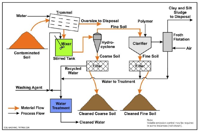
Figure 12-6. Soil washing process schematic.
Source: Federal Remediation Technologies Roundtable (https://www.frtr.gov/matrix/Soil-Washing/)
Treatment Mechanism: The concept of reducing PFAS soil contamination via particle size separation is underpinned by the preference of PFAS to sorb to soil fractions with high organic carbon content, promoting stronger hydrophobic interactions. Typically, finer soil fractions (for example, clays and silts) are enriched in organic carbon relative to coarser grained soil fractions (for example, sands and gravels). Therefore, using a fluid, such as water, to promote particle size separation can effectively segregate the soil fraction containing the highest PFAS impact. The PFAS impacted fine grained soil fraction can be further processed to minimize volume and managed separately for treatment or disposal from the coarser grained soil fraction. Several mechanical approaches can be implemented to facilitate the particle size separation process, including vibratory screens, trommels, hydrocylcones, and spiral classifiers (USEPA 1999).
During the soil washing process, the sorbed PFAS mass may transfer from the solid phase to the liquid phase through diffusion processes. Additionally, PFAS mass removal from impacted soil may be enhanced by promoting both desorption and dissolution into the liquid phase by flushing with water or an extraction solvent. PFAS extracted into the aqueous phase is then treated by other technologies (for example, GAC and/or IX) or staged for off-site disposal (ESTCP 2022). Leveraging desorption for PFAS mass reduction in impacted soil during the soil washing process is most effective for PFAS with lower distribution coefficients (i.e., less preference for the solid phase) and higher solubility in the wash solution.
State of Development: Soil washing is considered a field-implemented technology based on its history with other contaminants and has been evaluated for PFAS treatment efficacy in multiple field tests. The technology grew out of mining industry operations and was modified for environmental applications during the 1990s. It has historically been applied to soils contaminated with metals, semivolatile organics, and PCBs/pesticides (USEPA 1999; USEPA 1993). The same soil particle size separation and dissolution wash processes employed for these historical contaminants have been transitioned for application to PFAS-impacted soils based on similar physical and mass transfer properties. The transference of these separation and removal processes has been verified for PFAS-impacted soils by field demonstration projects performed to date. PFAS soil washing pilot/field demonstration projects have been performed at multiple Australian and U.S. sites (Quinnan et al. 2022; ESTCP 2022; Becker 2022). There are currently only a small number of vendors offering ex situ soil washing for full-scale applications. Further research and field studies are still required for alternative surfactants/extraction solutions that can be employed to remove PFAS more effectively from the finer grained soil fraction.
Effectiveness: A general guideline for contaminant reductions by soil washing is 90%–95% for the coarser grained soil fraction, assuming particle size separation of the coarser grained soils and mass transfer to the liquid phase for follow-up treatment/removal.
Results from an ESTCP pilot test confirmed that coarser grained sand and gravel fractions met performance goals, while the finer grained fraction was segregated for later treatment or disposal. The grain size composition was approximately 30% gravel, 40% sands, and 30% fines. Approximately 180 tons of PFAS-impacted soil was treated. Baseline PFOS concentrations detected in composite samples representing combined particle sizes ranged between 3.9 and 740 µg/kg, while detected baseline total PFAS concentrations ranged between 5.38 and 874 µg/kg. PFOS removal efficiencies were generally highest in the gravel fraction (94.6%–98.1%), followed by the sand fraction (88.6%–96.1%), and the finer grained fraction (-7.7%–61.8%, where variability in the PFAS concentrations in the finer grained fraction is thought to have caused the negative removal efficiency). The removal efficiencies for total PFAS for the coarser grained fraction were generally higher than PFOS for each stockpile, indicating that the soil washing process was effective at removing other PFAS (Quinnan et al. 2022; ESTCP 2022).
Another field-scale soil washing demonstration investigated the treatment of approximately 573 cubic yards of PFAS‐impacted loamy sandy soil and sediments. Baseline stockpile characterization for PFOS concentrations ranged between approximately 3,000 µg/kg and 12,000 µg/kg for the coarser and finer soil fractions, respectively. Following two rounds of soil washing treatment, the coarser grained soil fraction showed a PFOS reduction of 99% while the finer grain soils PFOS reduction was 89%. Because of the particle size separation, the total soil volume requiring off-site disposal was reduced by more than 90% (Becker 2022; ESTCP 2022).
Design/Operating Considerations: Determining the soil grain size distribution, as well as PFAS concentrations within the various grain size types, are the key design/operating considerations. Since soil particle size separation represents the primary PFAS removal/soil volume reduction mechanisms, soil washing is less cost-effective as the percentage of finer grained soils increases. A particle size distribution of 0.25–2 millimeters is considered optimal for soil washing, while <0.063 millimeters may not be viable, which correlates to <25% silts and clays considered optimal and >50% may not be viable (USEPA 1990; 1997). High clay content with corresponding high moisture levels poses a material handling and feed challenge. Heterogeneity and inconsistent feed conditions can also impact PFAS removal efficiency, which can require preprocessing for homogenization. Soils may need to be segregated by order of magnitude concentrations and treated using different process conditions to optimize treatment throughput and minimize treatment costs. Other key process parameters include soil throughput, retention time, contaminant solubility, wash solution to soil ratios, soil cation exchange capacity, and design parameters associated with the wash solution treatment and soil dewatering processes.
Sustainability: Intensive energy usage is required for the various material handling, separation, and liquids treatment operations. The generated wash solution requires treatment but can be recycled for continuous reuse. Treated soils can potentially be redeposited on site if applicable regulatory criteria are met, which avoids off-site disposal. Separated finer grained soils that do not meet regulatory criteria require off-site disposal.
Related Ongoing Research Funded by SERDP:
- ER20-5258 Ex Situ Soil Washing to Remove PFAS Adsorbed to Soils from Source Zones
12.4 Incineration
Because of the increasing interest in incineration from the public, press, and regulatory community, and the potential application of incineration to liquids or solids, the following information is being provided as a separate section. The Priority Topics for Treatment Technologies include updated information for incineration, pyrolysis/gasification, and thermal desorption (see Section 1.6.1).
Treatment Description: Incineration is defined as “burning hazardous materials at temperatures high enough to destroy the contaminants” (USEPA 2012). Incineration is destruction (mineralization) using combustion, which requires heat and oxygen. Heat is applied directly to the PFAS-contaminated solids (soil/sediment/spent adsorbents/waste) or liquids (AFFF/water/wastewater/leachate/chemicals). Vaporized combustion products can be captured (precipitation, wet scrubbing) and/or further oxidized at elevated temperature. Pyrolysis and gasification are related thermal treatment technologies. Some additional information about pyrolysis and gasification is discussed in Section 12.5, thermal treatment for air sources and in 12.7.2 thermal treatment for solids.
State of Development: Incineration is a mature technology that has been used for various solid and liquid wastes, but its ability to remove PFAS from waste streams is a topic of study. The USEPA has compiled a PFAS Thermal Treatment Database (USEPA 2022) to help synthesize the current body of research.
Effectiveness: Incineration is one of only a few technologies that can potentially destroy PFAS, though the conditions required to destroy PFAS are not well understood (USEPA 2024). In December 2020, USEPA released a draft interim guidance on destruction and disposal of PFAS (USEPA 2020) and Version 2 was released in April 2024 (USEPA 2024). Recent testing and reporting of PFAS destruction by incineration has documented destruction efficiencies of greater than 99 percent for some PFAS (Barr Engineering 2022; Chemours 2023; EA Engineering 2021).
There are multiple areas of active research to evaluate the effectiveness of incineration which initially focused on destruction temperatures and treatment times. Ongoing research is also assessing the potential of incineration to generate byproducts of incomplete combustion, to analyze stack gas, to understand deposition onto land, and to manage incinerator wastes, along with other potential risk factors.
In April 2022, in response to a congressional requirement in the National Defense Authorization Act (NDAA), the Department of Defense (DOD) placed a temporary ban on incineration of PFAS-containing materials generated by the DOD up until such time as a PFAS disposal policy was developed consistent with USEPA (2020) and Section 343 of the 2022 NDAA. The DOD published a memo with interim guidance about destruction or disposal of materials containing PFAS, including AFFF that has been taken out of service, on July 11, 2023 (USDOD 2023). The DOD interim PFAS disposal guidance supersedes the previous temporary moratorium and is expected to be updated annually. USDOD (2023) identifies the following PFAS disposal options in order of prioritization: 1) Spent GAC reactivation at a RCRA permitted facility; 2) landfilling at a permitted RCRA Subtitle C hazardous waste facility; 3) landfilling at a permitted RCRA Subtitle D non-hazardous solid waste facility with an appropriate leachate and gas collection and management system; and 4) incineration at a permitted RCRA Subtitle C hazardous waste facility. Publicly available air testing results for PFAS incineration destruction efficiency and byproducts of incomplete combustion were considered in the development of the DOD interim PFAS disposal guidance, while ongoing PFAS incineration research and updates to USEPA (2020) will be incorporated into the future annual updates. A follow-up statement was published on July 17, 2023 about additional planning and coordination that is needed before incineration is implemented (USDOD 2023).
Design/Operating Considerations: Waste incinerators are fixed facilities. Federal and state permits dictate the materials processed, core incinerator operations (for example, temperature and time, turbulence), and control of process air, liquid, and solid wastes. Permit and design/construction similarities reduce the operational and performance differences between individual incinerators.
When considering waste disposal options, transportation costs, energy costs, regulatory approvals, and final disposition of process waste residues should be evaluated, as these differ among incineration facilities.
Sustainability: The environmental footprint for incineration includes transportation and supplemental fuel for the incineration process. Incineration of contaminated soil, liquid wastes, and IDW is energy-intensive and PFAS emissions, including potential PFAS combustion byproducts, from incinerators are currently not well understood (USEPA 2020). Truck hauling traffic affects the local community by creating additional traffic congestion, noise, and particulate matter emissions. The cost for this approach is high, but the solution may be cost-competitive for smaller treatment volumes.
Related Past, Ongoing, and Recent Research Funded by SERDP:
- ER19-1408 Analysis of Fate of PFAS during Incineration
- ER22-7470 Development and Application of Injectable Fuels/Adjuncts for In Situ Treatment of PFAS and Co-Occurring Chemicals in Source Areas by Smoldering Combustion
12.5 Air Treatment Technologies
PFAS vapors or particles can be generated during any activity that involves PFAS or materials containing PFAS. The multitude of sources for PFAS-containing vapors and particles, some of which are unique due to their specific function (for example, industrial or commercial processes), is complicated by a lack of basic understanding of the chemical and physical properties for PFAS that are not used as widely. Additionally, air emissions should be considered as part of any PFAS-related activity, regardless of whether it is the primary media being treated. For example, during landfill leachate treatment, air emissions could be generated, requiring treatment.
PFAS vapors or particulates may be captured by conventional air pollution control (APC) equipment that has been historically developed to control vapors, particles, and fine dusts emitted from permanent industrial sources or temporary environmental or construction sites. Though the effectiveness of conventional APC technologies in removing PFAS from air streams is not well understood, current practice is to apply these methods and practices of vapor and dust control that are presently used or required for similar equipment and processes. The performance of these technologies should continue to be researched and documented with a focus on those PFAS that can be reliably quantified. Specific research needs for the emissions from thermal treatment technologies, including those related to APC equipment, are discussed in USEPA (2024, section 3.a).
A standardized method for stack testing for PFAS emissions has only recently been developed (see Section 11.1.7.12), and stack testing to date has primarily focused on the overall removal efficiency for the destruction technology being evaluated (for example, see Barr 2022). Sampling stack emissions and performing adequate analysis is an active area of research and will need to be a part of assessing adequate treatment of any stack emissions thought to contain PFAS. Additional information on the effectiveness of thermal treatment technologies is included in Section 12.7.2.
12.5.1 Conventional Air Pollution Control (APC) Technologies
PFAS vapors may be captured by conventional APC equipment. However, this does not mean that older methods do not need to be tested to document their performance, nor does it mean the older methods should not be modified or entirely redesigned to account for PFAS. Rather, it means that conventional APC technologies that can treat vapors and particles containing PFAS may have some level of removal efficiency and should be evaluated to ensure appropriate capture or destruction is taking place.
Thermal treatment technologies for PFAS contained in emissions are an area of focus in the research community. A limited number of these technologies have been implemented and are currently being evaluated for their efficiency.
Technologies and equipment for control of potential emissions can be placed in four groups: 1) those that capture PFAS-containing particles; 2) those that capture PFAS-containing vapors, 3) those that capture PFAS in both vapors or particles, and 4) those that destroy PFAS in the air stream being emitted from the process. Destruction of PFAS through thermal oxidation and incineration is briefly covered here and is also covered in Section 12.4. Particle capture and vapor capture are further described below. More information about specific air pollution control technologies is available from USEPA (2022), which is a web site with links to individual technology fact sheets.
12.5.1.1 Particle Capture
PFAS that are fully partitioned to particulate matter in the air stream could be removed by particle capture mechanisms:
- Bag houses and similar units rely on filter media whose pore openings are smaller than the smallest targeted particle or particulate. The nature of the targeted material is less important than its overall size and smallest dimension. The filter material may be configured as a bag or a sheet. Either may be flat or pleated to increase its surface area within a specific area perpendicular to the air flow.
- Cyclones accelerate the speed of a particle as it travels a circular path that continually decreases in diameter. As the same amount of air is forced through a smaller cross section, its velocity increases. The weight of a particle or particulate becomes the force that pushes it to the outer diameter of the spiral. A collection point in the design diverts the slice of total air flow containing all particles traveling along the outer wall to a collection vessel. This method generally works best when the air is relatively dry so that the solids do not adhere to the walls of the cyclone.
- Wet scrubbers add a liquid (typically water) to the air stream being treated. They are used to control airborne vapor and particles. There are two main reasons for the addition of water:
- Water adsorbs to the particle to increase its weight and accelerate its settling under the force of gravity. The air flow is often horizontal to the unit, and the cross-section of the wet scrubber increases greatly (at least an order of magnitude) immediately after the point where the liquid is introduced.
- Water in the liquid droplets, mist, or fine spray provides enormous area through which water-soluble or miscible vapors may dissolve. The rapidity of this transformation is important because the time the air stream is exposed to water droplets or vapors are in contact with the air stream is typically very limited.
- Wet-scrubber air often flows horizontally to allow more volume or area for the particles to fall or settle.
- Wet scrubbers (or scrubber towers) through which air travels vertically and is discharged at the top often employs a greater mass or volume of water to a given mass of particles or vapors than a horizontal configuration. This provides more water particle surface area and higher humidity, which improves capture of vapors and/or particles.
- Electrostatic precipitators (ESPs) contain one or more grids of fine wires perpendicular to the air flow. Electrical current applied to the grids creates a small, opposite charge on particles in the air or changes the charge on individual particles. These charges are intended to enhance the capture of particles on the charged grids and potentially other surfaces of the unit. Low humidity in the air to be treated is desirable.
12.5.1.2 Vapor Capture
APC technologies that specifically target vapors are few, though the use of various media allows capture of specific contaminants or mixtures of contaminants better than on one medium. The most common vapor treatment technique is adsorption of vapors, which may contain PFAS, from the treated airstream onto media. Media may include granular activated carbon, raw or coated clays, or synthetic resin. Some media may capture numerous PFAS while others perform better for groups (for example, short- or long-chain compounds or those with specific subgroups). The evaluation of the efficiency of these technologies depends on important operating conditions such as the empty-bed contact time (EBCT), which can vary for each media type. Typical vapor control EBCTs range from seconds to a minute. Very fine (powdered) dry media can be injected into the air stream in special cases. However, the practice is unusual in environmental remediation and creates an additional waste stream (that is, the powdered media) that must be managed. These technologies will require continued evaluation and ongoing research to ensure that the objectives for PFAS removal in the air stream are adequate.
12.5.1.3 Thermal Treatment
The use of thermal treatment for PFAS destruction in stack emissions is a topic of current research and is dependent on having reliable methods for sample collection and analysis of PFAS contained in those emissions. Pyrolysis, gasification (see Section 12.7.2), and thermal oxidation are being investigated for their use and efficiency on PFAS-laden air streams. Some investigations have shown significant levels of PFAS removal using these methods (Winchell 2022; Chemours 2020; Barr 2022). Continued data collection on the efficiency of these systems will guide this important management option to control PFAS in stack emissions in the future. The Priority Topics for Treatment Technologies include updated information for incineration, pyrolysis/gasification, and thermal desorption (see Section 1.6.1).
12.6 Limited Application and Developing Liquids Treatment Technologies
The treatment technologies presented in this document are provided in a hierarchy defined in Section 12.1, which is based on level of implementation and confidence derived from widespread, well documented examples. The three development levels are: field-implemented technologies, limited application technologies, and developing technologies. Both in situ and ex situ technologies are included in this section. It is not always clear if a limited application or developing technology may be effective in situ, ex situ, or both; therefore, further distinction is not made in this section.
The field-implemented technologies described in the preceding sections have been applied at multiple sites and are well documented in the available literature. In addition to these well-demonstrated technologies, many technology approaches have been tested in academic and other research laboratories at the bench scale or have progressed as far as field pilot tests or limited field applications. These limited application technologies are briefly summarized in the Table 12-1 Treatment Methods Table Excel File. Additional information is provided in the following sections.
Not all of these limited or developing technologies have been demonstrated as suitable or effective under multiple treatment scenarios. For instance, destructive technologies, such as electrochemical oxidation, nonthermal plasma, hydrothermal alkaline treatment, and supercritical water oxidation, have been shown to be effective for treatment of high concentration, low volume liquids but may be less suitable for high volume, low concentration liquids.
Related Past, Ongoing, and Recent Research Funded by SERDP:
- ER18-1026 Rational Design and Implementation of Novel Polymer Adsorbents for Selective Uptake of Per- and Polyfluoroalkyl Substances from Groundwater
- ER18-1515 Cost-Effective Destruction of Per- and Polyfluoroalkyl Substances from DoD Subsurface Investigation-Derived Wastes using a New Class of Adsorptive Photocatalysts
- ER18-1417 Molecular Design of Effective and Versatile Adsorbents for Ex Situ Treatment of AFFF-Impacted Groundwater
- ER18-1395 Electrically Assisted Sorption and Desorption of Per- and Polyfluoroalkyl Substances
- ER18-1052 Remediation of Per- and Polyfluoroalkyl Impacted Groundwater Using Cationic Hydrophobic Polymers as Ultra-High Affinity Sorbents
- ER21-1018 Destruction of PFAS by Hydrodynamic Cavitation
12.6.1 Sorption Technologies
12.6.1.1 Coated Sand
Polymer-coated sand is an adsorbent material that has high affinity for organic contaminants. Cyclodextrin molecules are polymerized by a cross-linking agent and form inclusion complexes with many organics. The adsorbent material has two components: (a) polymer coat (active component that removes the contaminants) and (b) support base (inactive component); the combination of both provides an adsorbent with high selectivity and mechanical stability.
The adsorbent showed similar performance in removing PFOA and PFOS as GAC, but one of the key features of this technology is the high regenerability of the adsorbent (filter) for reuse (Bhattarai, Manickavachagam, and Suri 2014). Another important feature of the technology is that it can remove other organic pollutants such as chlorinated solvents (for example, trichloroethene (TCE), perchloroethylene (PCE), hexavalent chromium, and others (Badruddoza, Bhattarai, and Suri 2017). Surface modification has been shown to improve the adsorption of PFOS (Zhou, Pan, and Zhang 2013) by using organic polymeric surfactants.
Related Ongoing Research Funded by SERDP
- ER20-5100 In Situ PFAS Sequestration in AFFF-Impacted Groundwater
- ER20-5182 Validation of Colloidal Activated Carbon for Preventing the Migration of PFAS in Groundwater
12.6.1.2 Zeolites/Clay Minerals (Natural or Surface-Modified)
Zeolites are naturally occurring aluminosilicate compounds that are widely used in chemical separation and purification due to their high surface area and small uniform pore size among other properties (Tao et al. 2006). Zeolites are also being increasingly considered as a medium for the sorption of various pollutants, including cationic heavy metals, ammonium, and some volatile organic compounds, due to the aforementioned properties, as well as their high ion exchange capacity and low cost (Delkash, Ebrazi Bakhshayesh, and Kazemian 2015). Clay minerals, including natural and surface-modified (see below), are also used as adsorbents and are similar to zeolites in composition but have different crystalline or chemical structure. Surface-modified clays have been reported to have enhanced adsorption performance for a variety of organic and inorganic constituents (Han et al. 2019), as well as for PFAS (Zhou et al. 2010, 2013).
Both zeolites and clay minerals can be used ex situ (that is, pump and treat) by being placed in packed-bed flow-through vessels or in situ via injection into aquifers. In situ applications of these materials are lacking in study or field application. Most available literature is limited to academic laboratory experiments (Ochoa-Herrera and Sierra-Alvarez 2008; Punyapalakul et al. 2013; Zhou, Pan, and Zhang 2013; Zhou et al. 2010). Du et al. (2014) and Arias Espana, Mallavarapu, and Naidu (2015) provided comprehensive literature reviews.
Zeolite and clay minerals use both ion exchange and adsorption mechanisms to remove PFAS from water. These materials exhibit widely varying PFOS and PFOA adsorption capacities (Du et al. 2014), so PFAS adsorption performance should be assessed for each specific zeolite or clay-based media. However, synthetic processing of zeolite can create highly siliceous material (Baerlocher 2007) or can incorporate cationic surfactants into the surface structure (aka surface-modified zeolites–SMZ) (Jiménez-Castañeda and Medina 2017). One study indicated that engineered zeolites with a high Si/Al ratio were effective at adsorption of PFOS, presumably due to hydrophobic interactions rather than ion exchange (Ochoa-Herrera and Sierra-Alvarez 2008).
Surface-modified clays are made by intercalating a modification agent into the clay that has a high affinity for specific classes of contaminants. For PFAS adsorption, the modification agent is attached to the clay via cation exchange sites and includes electrostatic and hydrophobic moieties that are highly specific for PFAS. Mechanistically, PFAS molecules diffuse into the interlayer space of the surface-modified clay and then are bound through ionic and van der Waals forces with the fixed modification agent (Yan et al. 2021).
Two modified clay-based adsorbent products are identified as being used in field pilots or small-scale field trial applications (Arias et al. 2013; Arias Espana, Mallavarapu, and Naidu 2015) to treat PFOA and/or PFOS.
A commercially available surface-modified clay was successful at adsorbing a variety of PFAS from AFFF-impacted groundwater. The media was resistant to fouling by groundwater constituents, such as natural organic matter, and common co-contaminants (diesel, TCE, and 1,4-dioxane) (Yan et al. 2020). Laboratory and pilot-scale column testing of surface-modified clay for PFAS removal from contaminated groundwater that is to be used for drinking water showed PFOS and PFOA removal to the treatment target (2 ng/L). This media demonstrated a shorter empty bed contact time (EBCT) and longer media bed life than 13 other adsorbents (Pannu and Plumlee 2021; Hwang and Grieco 2021). PFAS adsorption (short- and long-chain) by using surface-modified clay with a variety of water types was examined in Grieco et al. (2021) and Najm et al. (2021).
High silica materials, such as H-form synthetic mordenite (HSM) and Y-form sodium zeolite (NA-Y80), and hydrotalcite clay provided adsorption capacities that were equivalent or exceeded powdered activated carbon (PAC). Surfactant-modified clays also performed as well as or better than PAC. It should be noted that none of these studies were conducted in flow-through column experiments, so applicability to ex situ treatment systems cannot be assessed. Arias Espana, Mallavarapu, and Naidu (2015) stated that organoclays, clay minerals, and highly siliceous materials have fast kinetics (0.4–3 hr to reach equilibrium), making them suitable for remediation applications.
Related Past, Ongoing, and Recent Research Funded by SERDP:
- ER18-1526 Complete Reductive Defluorination of Poly- and Perfluoroalkyl Substances (PFASs) by Hydrated Electrons Generated from 3-Indole-acetic-acid in Chitosan-modified Montmorillonite
- ER21-1238 Sustainable PFAS Treatment Using Layered Double Hydroxide (LDH) Sorbents
- ER22-7482 Demonstration-scale Evaluation of a Novel Surface-modified Clay Adsorbent: Comparison of Fluoro-Sorb, GAC, and IX Resin for the Removal of PFAS and Co-Contaminants in Groundwater
12.6.1.3 Biochar
Biochar is a hybrid word rooted in the words “biomass” and “charcoal.” Biochar is a carbon-rich porous solid that is synthesized by heating biomass, such as wood or manure, in a low oxygen environment (Ahmad et al. 2014). Biochar may be produced by pyrolysis of PFAS-impacted media (Thoma et al. 2021). This material has primary applications for carbon sequestration, improvement of soil fertility, and most recently as an adsorbent for pollutant removal. Biochar is characterized to have high affinity for organic contaminants, which is dependent on both the pore structure and the surface functional groups of the biochar material (Guo et al. 2017).Some of the key factors controlling the properties of biochar (for example, pore size composition and hydrophobicity) include the temperature of pyrolysis and biomass feedstock, among others. In many respects, the properties of biochar are similar to but generally lower than those of GAC for sorptive purposes.The variability of biochar with regard to performance parameters and quality control makes it challenging to implement on a large scale, and procuring large volumes of consistent materials and meeting design specifications can be challenging at large scales.
The available literature is limited to academic laboratory batch experiments on the bench-scale (Chen et al. 2011; Inyang and Dickenson 2017; Kupryianchyk et al. 2016; Rahman et al. 2014; Xiao, Ulrich, et al. 2017), with one published study reporting pilot-scale column operation (Inyang and Dickenson 2017).
Related Past, Ongoing, and Recent Research Funded by SERDP:
- ER22-3150 Engineering an “All-in-One” Biochar-Surfactant System for Enhanced PFAS Sorption and Reductive Degradation Using a Coupled Ultraviolet and Ultrasonication Approach
- ER22-3157 Hydrothermal Destruction of Per- and Polyfluoroalkyl Substances during Designer Biochar Reactivation
- ER23-3593 Tailored Carbonaceous Materials as Biofilter Amendments for PFAS Removal in Stormwater Runoff
12.6.1.4 Hydrogels and Fluorogels
Efficient removal of short-chain PFAS from water can be achieved using hydrogels and fluorogels because of their high selectivity and affinity for these compounds (Ateia et al. 2019; Kumarasamy et al. 2020). For example, Ateia et al. (2019) demonstrated selective, rapid removal of 16 PFAS using cationic polymer (hydrogel) poly (N-[3-(dimethylamino)propyl] acrylamide, methyl chloride quaternary (DMAPPAA-Q). While adsorption was not reversed in a standard environmental matrix, regeneration was possible using a simple solvent/salt matrix. Performance was maintained in six consecutive sorption/regeneration cycles.
Related Past, Ongoing, and Recent Research Funded by SERDP:
- ER22-3415 Novel Swellable Ionomers for Enhanced PFAS Sorption and Destruction
- ER22-3155 In situ Sequestration of PFAS from Impacted Groundwater Using Injectable High Affinity Cationic Hydrophonic Polymers
12.6.2 Precipitation/Coagulation/Flocculation
Precipitation/coagulation/flocculation is a common pretreatment approach used in wastewater treatment plants for removing various particles and dissolved constituents. Coagulants, either commodity or proprietary chemicals, can be added to water (conventional technology) or generated by anode-cathode reactions of metal plates inserted into the water (electrocoagulation). Common examples include:
- inorganic cationic coagulants (for example, alum, iron-based)
- commodity (for example, polyDADMAC) and specialty (for example, Perfluorad) polymers
- electrochemical precipitation
Coagulants assist in the formation of solids. Flocculation is typically conducted by adding a soluble polymer and slowly mixing to allow the particles to agglomerate and grow. Upon solid formation, constituents such as PFAS can be physically incorporated into, or sorbed onto, the flocculated particulate (which is known as co-precipitation). The precipitated solids are then separated from the water by sedimentation and/or filtration processes. The solid material containing the PFAS requires disposal, see the Table 12-1 Treatment Methods Table Excel File and Section 12.3.2.
Literature documents only bench-scale study results on treating PFAS via precipitation, flocculation, or coagulation; therefore, this is considered a partially developed technology. Evaluations have focused on conventional commodity chemical coagulation (for example, aluminum or ferric salts) and nonconventional coagulation (for example, proprietary chemical coagulants or electrocoagulation). Pilot- and full-scale applications have not been documented in the United States (Birk 2017), and specialty materials for PFAS applications will require strict quality control to ensure that performance characteristics are consistent.
Nonconventional precipitation (for example, electrocoagulation or advanced chemical precipitants) has shown more potential for direct PFAS treatment, but has very limited data. High-affinity cyclodextrin polymer has been tested in bench-scale reactors and was found to have superior removal capacity to GAC (Xiao, Ling, et al. 2017).
Electrocoagulation reactors, which range from basic to very sophisticated designs, have been reported to be highly efficient, compact, relatively low cost, and completely automatable (Baudequin et al. 2011; Lin et al. 2015). Recent studies have found that PFAAs, such as PFOA and PFOS, can be quickly sorbed on the surface of zinc hydroxide particulates generated by electrocoagulation (Lin et al. 2015).
Related Past, Ongoing, and Recent Research Funded by SERDP or ESTCP:
- ER-2425 Development of a Novel Approach for In Situ Remediation of PFC-Contaminated Groundwater Systems
- ER18-1026 Rational Design and Implementation of Novel Polymer Adsorbents for Selective Uptake of PFASs from Groundwater
- ER20-5370 Sustainable Firefighting System Cleanout and Rinsate Treatment Using PerfluorAd®
- ER22-3194 Green Remediation of PFAS in Soil and Water
12.6.3 Redox Manipulation
Redox manipulation includes chemical oxidation and reduction technologies. These have been summarized in more detail in Nzeribe et al. (2019). Chemical oxidation for PFAS is a technology approach that is achieved via the delivery of liquid, slurry, or gaseous oxidants to transfer electrons from a reactive oxidant species to a target (PFAS) and affect the cleavage of atoms in the PFAS molecular structure. Carboxylic or sulfonic group “heads” (functional groups) of PFAS are commonly more susceptible to redox transformation than the fluorinated carbon chain “tails.” There is a lack of robust evidence of defluorination via chemical oxidation processes. The mechanisms involving multiple species of free radicals that trigger PFAS oxidation are not well understood. PFAA precursors are also known to be oxidized to form persistent and terminal PFAAs without further oxidation (Houtz and Sedlak 2012; Anumol et al. 2016). Consequently, care should be taken to monitor site and plume conditions and understand potential formation and transport of transformation products.
Additional mechanistic studies are needed to develop chemical oxidation as a feasible PFAS remediation approach and to further assess factors that may promote or limit this technology. Common oxidants that have been documented to treat PFAS and other organic contaminants (for example, chlorinated solvents) include ozone, catalyzed hydrogen peroxide, and persulfate, as discussed further below. The impacts of co-contaminants, quenching reactions, and metals mobilization are also considerations for redox-based remedies (for example, ITRC 2005, 2011).
12.6.3.1 Ozone-Based Systems
Ozone can be coupled with other oxidants such as hydrogen peroxide and persulfate to promote the generation of a suite of aggressive free radicals capable of degrading PFAS. An ozone-based system was implemented for the treatment of PFAS in a single field-scale test by Eberle, Ball, and Boving (2017) using combined ozone and activated persulfate.
The main pathway and mechanism behind the ozone-based system tested by Eberle, Ball, and Boving (2017) is unknown, as detailed mechanistic studies have not been performed. However, they suggested that PFAS reduction in groundwater after treatment was not limited to partial degradation, but it is possible that sorption also had a role to play in the declining aqueous PFAS concentration. They postulated that activated persulfate could lead to a decline in pH, thereby increasing sorption of PFAS to soil due to increased protonation.
This approach has been partially demonstrated in one field-scale setting, and results are encouraging for application using ex situ or in situ approaches. However, because there is an absence of supporting mechanistic data, it is likely that other factors could come into play that may promote or limit this technology.
The application of the ozone-based system for the treatment of PFAS has also been evaluated in bench studies (Lin et al. 2012; Kerfoot 2014; Huang et al. 2016; Eberle, Ball, and Boving 2017; Thomas et al. 2020). Lin et al. (2012) and Thomas et al. (2020) tested ozone systems without and inclusive of hydrogen peroxide addition in alkaline environments, and Kerfoot (2014) used hydrogen peroxide and ozone bubbles for a bench-scale test of groundwater from a monitoring well foam firefighting site in Canada. Huang et al. (2016) combined ozone with photolysis to produce hydroxyl radicals and photogenerated electrons. Dai et al. (2019) tested combinations of ultraviolet light, ozone, and air fractionation, and reported that ozonated air fractionation provided more than 95% reduction in PFAS concentrations.
In the field demonstration, PFAS concentrations in groundwater were reduced by 21–79% after treatment. Also, an initial pilot test at a fire training area using ozone and peroxide has shown removal of 98.5% and 92.3% for PFOS and PFOA, respectively, in groundwater and over 80% for PFOS on saturated soil with proportional release of fluoride (Kerfoot 2016).
In bench-scale studies, Eberle, Ball, and Boving (2017) decreased PFAS by 99.9% using PFAS-contaminated site groundwater and spiked deionized water. Eberle, Ball, and Boving (2017) also reported that the system was not sensitive to other groundwater organics. Kerfoot (2014) reported 89.8% removal of PFOS and > 80% for other PFAS (PFPeA 89.8%, PFHxA 86.2%n and PFHxS 98.1%). These studies, however, do not confirm destruction through mass balance and analysis of byproducts.
Each of these approaches and test conditions used different water matrices and starting concentrations. It is difficult to state whether published regulatory levels can be achieved in practice with these technologies, but in general they appear to be effective as a polishing technology to achieve low part-per-trillion treatment requirements.
Related Ongoing Research Funded by SERDP:
- ER18-1545 Enhanced Oxidative Destruction of PFAS in Investigation-Derived Waste Soil and Water
12.6.3.2 Catalyzed Hydrogen Peroxide (CHP)–Based Systems
CHP is one of the strongest oxidant systems used in environmental remediation. It involves reaction of hydrogen peroxide with a catalyst to predominantly generate hydroxyl radicals. Some CHP systems produce nucleophiles and reductants, including superoxide and hydroperoxide (Mitchell et al. 2014). Common catalysts include transition metals such as iron (Fenton and Fenton-like reaction) or manganese, chelated metals, and naturally occurring minerals, for example, Watts et al. (2005) and Teel et al. (2007).
Hydroxyl radicals attack the alkyl groups of both PFCAs and PFSAs, but do not attack the perfluoroalkyl chain. As a result, PFCA and PFSA precursors are transformed to PFCAs of related perfluorinated chain length (Bruton and Sedlak 2017). Mitchell et al. (2014) demonstrated that superoxide and hydroperoxide (which are nucleophiles and reductants generated as a reaction in CHP but are not chemical oxidants) generated in alkaline pH CHP systems mineralize PFOA but did not elucidate a mechanism.
Bench-scale testing has been successfully demonstrated. Field deployment of hydroxyl radical-based CHP systems may be limited due to decomposition of PFAS precursors to PFOA and other PFCAs as unreactive transformation products (Bruton and Sedlak 2017).
CHP systems that predominantly generate hydroxyl radicals partially transform PFAAs to their PFCAs of related perfluorinated chain length, which are not further transformed (Houtz and Sedlak 2012; Bruton and Sedlak 2017). Systems that generate superoxide and hydroperoxide have been demonstrated at the bench test level to mineralize PFOA (Mitchell et al. 2014), but effectiveness with other PFAS is unknown.
12.6.3.3 Activated Persulfate
Persulfate anion (S2O82-) is activated to generate reactive radical species, primarily sulfate radicals (2.6 volts, or V) and hydroxyl radicals (2.7 V). Methods to activate persulfate include transition metals, high pH, and heat activation (Siegrist, Crimi, and Simpkin 2011). Hydroxyl radicals are the predominant radicals formed at high pH conditions (Furman et al. 2011), while at acidic pH there is greater yield of sulfate radicals (Siegrist, Crimi, and Simpkin 2011).
PFCAs are attacked by sulfate radicals under acidic conditions, initiating a decarboxylation reaction, where cleavage of the carbon-to-carbon (C-C) bonds occurs between PFCAs and the carboxyl group (-COOH), forming unstable perfluoroalkyl radicals (CnF2n+1) (Hori et al. 2010; Lee et al. 2012; Yin et al. 2016). A stepwise series of decarboxylation and hydrogen fluoride (HF) elimination reactions continues to form shorter chain PFCAs until all PFCAs are mineralized to fluoride and carbon dioxide. PFSAs such as PFOS are unreactive with sulfate radicals (Park et al. 2016; Bruton and Sedlak 2017). Hydroxyl radicals attack the alkyl groups of both PFCAs and PFSAs, but do not attack the perfluoroalkyl chain. As a result, PFCA and PFSA precursors are transformed to PFCAs of related perfluorinated chain length (Bruton and Sedlak 2017). Under alkaline pH conditions the sulfate and hydroxyl radicals are reactive with the alkyl groups but similarly unreactive with the perfluoroalkyl chain, which is the basis of the TOP method (Houtz and Sedlak 2012).
Activated persulfate under acidic conditions has proven effective for PFOA (PFCAs) with nominal 100% degradation, but PFOS is not transformed. Sulfate radicals and hydroxyl radicals generated by alkaline persulfate activation transform PFCA and PFSA precursors to PFCAs of related perfluorinated chain length (Bruton and Sedlak 2017).
Related Past, Ongoing, and Recent Research Funded by SERDP:
- ER-2423 In Situ Treatment Train for Remediation of Perfluoroalkyl Contaminated Groundwater: In Situ Chemical Oxidation of Sorbed Contaminants (ISCO-SC)
- ER201729 Field Demonstration to Enhance PFAS Degradation and Mass Removal Using Thermally Enhanced Persulfate Oxidation Followed by Pump-and-Treat
- ER18-1545 Innovative Treatment of Investigation-Derived Waste Polluted with Per- and Polyfluoroalkyl Substance Contaminants and Other Co-Contaminants.
12.6.3.4 Sonochemical Oxidation/Ultrasound
The sonochemical process relies on the propagation of acoustic waves in liquids at frequencies ranging between 20 kHz and 1,000 kHz (Furuta et al. 2004), which results in cavitation. Operating parameters such as frequency (Campbell and Hoffmann 2015), power density (Hao et al. 2014), solution temperature, sparge gas, and initial concentration of PFAS (Rodriguez-Freire et al. 2015) play a significant role in the sonochemical degradation and defluorination rate of PFAS (Cao et al. 2020).
Sonochemical degradation occurs via two mechanisms: localized thermal treatment and free radical destruction (Rayaroth, Aravind, and Aravindakumar 2016). During cavitation, cyclic formation, growth, and collapse of micro/nano bubbles result in an intense increase in temperature and pressure (5000 Kelvin (K) and 2000 atmosphere (atm)), along with the generation of free radicals (Furuta et al. 2004; Chowdhury and Viraraghavan 2009).
Sonochemical oxidation has been successfully applied for rapid degradation of PFAS to fluoride (F–), sulfate (SO42-) and carbon dioxide (CO2). Vecitis et al. (2008) reported a complete recovery of SO42- and >90% defluorination of PFOA and PFOS with initial concentrations of 0.24 µM and 0.20 µM, respectively, for a field-scale application to treat groundwater from below a landfill. At bench scale, sonolysis has been reported in the literature as one of the most effective treatment processes for PFAS-contaminated water, because they almost immediately mineralize to SO42-, CO2, carbon monoxide (CO), and F– after cleavage of their C-C/C-S bond. Studies have reported >90 percent degradation and defluorination for PFOA and PFOS (Moriwaki et al. 2005; Vecitis et al. 2008; Cheng et al. 2008, 2010). Gole et al. (2018) demonstrated removal and defluorination of AFFF in a 91-L sonolytic reactor. Lei et al. (2020) showed a synergistic treatment effect of a combined persulfate/ultrasound approach.
Related Past, Ongoing, and Recent Research Funded by SERDP:
- ER21-5045 Sonolysis-based In Situ PFAS Treatment within an HRX Well
- ER21-1018 Thermal Destruction of PFAS by Hydrodynamic Cavitation
- ER22-3394 Pulsed Electrosorptive Cavitation: A Cohesive Approach for Complete Mineralization of PFAS in Aqueous Systems
- ER22-3150 Engineering an “All-In-One” Biochar-Surfactant System for Enhanced PFAS Sorption and Reductive Degradation Using a Coupled Ultraviolet and Ultrasonication Approach
12.6.3.5 Photolysis/Photochemical Oxidation
A thorough review of photolysis/photochemical oxidation technology for PFAS decomposition is reported in Wang et al. (2017). Chen, Zhang, and Liu (2007) and Giri et al. (2011) reported removal of PFAS by direct photolysis at 185 nm. Hori et al. (2004) and Chen, Zhang, and Liu (2007) reported that direct photolysis at 254 nm alone is not very effective because PFAS do not absorb light at wavelengths >220 nm due to their chemical structure. Chemical reagents/catalysts such as Fe3+, S2O82−, TiO2, heteropolyacid photocatalyst (H3PW12O40), CO32−, and IO4− when combined with ultraviolet (UV) (>220 nm) light can effectively decompose PFAS (Hori et al. 2005; Chen and Zhang 2006; Zhang, Pan, and Zhou 2016; Hori et al. 2007; Wang et al. 2008; Cao et al. 2010; Gomez-Ruiz et al. 2018; Xu et al. 2020). This is due to generation of strong and reactive oxidative species such as OH•, H•, CO3•– and PFAS-Fe complexes. Photochemical oxidation of PFAS is said to be dependent on the light source (UV or vacuum ultraviolet), initial concentration of PFAS, environmental matrix, temperature, pH, and type of reagent used (Lin et al. 2012; Giri et al. 2012; Lyu et al. 2015, 2015; Xu et al. 2017). Use of non-traditional photocatalytic methods such as fixating a photocatalyst within a porous media (McIntyre et al. 2023; McIntyre et al. 2022; McIntyre et al. 2021; McIntyre and Hart 2021) or the use of boron nitride may enhance destructive performance (Qanbarzade et al. 2023).
The major degradation pathways involved in the photochemical oxidation of PFAS are direct photolysis and free radical reactions. The C-C bond between PFAS is cleaved with the COOH group to form perfluoroalkyl radicals (Hori et al. 2003; Hori et al. 2008), which then react with water and undergoes hydrogen fluoride elimination to form shorter chain compounds (Liu et al. 2017). These then undergo hydrolysis to form subsequent shorter PFAS (losing CF2 units). During direct photolysis, the C-C and C-S bonds of PFAS are broken by photoelectrons to generate perfluoroalkyl radicals and carbon dioxide (Wang et al. 2017).
Related Past, Ongoing, and Recent Research Funded by SERDP:
- ER18-1595 A Combined Photo/Electrochemical Reductive Pathway towards Enhanced PFAS Degradation
- ER18-1513 Effective Destruction of Per- and Polyfluoroalkyl Substances in Water by Modified SiC-based Photocatalysts
- ER18-1515 A Cost-Effective Technology for Destruction of Per- and Polyfluoroalkyl Substances from DOD Subsurface Investigation-Derived Wastes
- ER18-1599 Pilot-scale Assessment of a Deployable Photocatalytic Treatment System Modified with BiPO4 Catalyst Particles for PFAS Destruction in Investigation-Derived Wastewater
- ER19-1403 Validation of UV/TiO2 Activated Alkaline Media (CFM) for Destruction of PFAS in Concentrated Liquid Waste Streams
- ER22-3258 Chemical-free Light-driven Destruction of Per- and Polyfluoroalkyl Substances Using Non-toxic Boron Nitride (BN)
- ER22-3187 Destruction of PFAS using Plasmonic Photocatalysts
12.6.3.6 Electrochemical Treatment
Electrochemical treatment occurs via anodic oxidation; a variety of materials have been used as anodes. The treatment effectiveness of PFOS and PFOA using different anodes can vary significantly. Most research on PFAS, particularly PFOS and PFOA removal, has been conducted using a boron-doped diamond (BDD) electrode due to its mechanical, chemical, and thermal stability (Trautmann et al. 2015; Schaefer et al. 2017; Schaefer et al. 2019; Wang et al. 2019; Smith et al. 2023). Some other electrodes, such as lead dioxide (PbO2), titanium oxide (TiO2), titanium suboxide (Ti4O7), and tin oxide (SnO2), also have the ability to treat PFAS-contaminated water (Ochiai et al. 2011; Zhou et al. 2012; Zhao, Gao, et al. 2013; Liang 2017; Liang et al. 2018). Operating conditions and parameters such as pH (Lin et al. 2012; Zhou et al. 2012), current density, electrolyte type (Song et al. 2010; Zhuo et al. 2012), electrode distance (Lin et al. 2012), initial PFAS concentration, and temperature are important factors that influence electrochemical oxidation of PFAS (Niu et al. 2016).
Electrochemical treatment proceeds via direct and indirect anodic oxidation (Radjenovic and Sedlak 2015; Niu et al. 2016; Schaefer et al. 2018). In direct electrolysis, contaminants are adsorbed onto and degraded directly at the electrode, while in indirect electrolysis, contaminants are degraded in the bulk liquid in reactions with oxidizing agents (that is, hydroxyl radicals) formed at the electrode (Radjenovic and Sedlak 2015).
Bench-scale studies have shown success in the degradation and defluorination of PFAS, including short-chain, long-chain PFAAs as well as PFAA precursors (Chiang 2018). Electrochemical oxidation of precursors may lead to the transient generation of perfluorinated carboxylates (Schaefer et al. 2018). Ultimately, fluoride is released, with typical recoveries ranging from 60 to 80%; the fate of the remaining fluoride is unknown, but studies have suggested that losses due to volatile perfluorinated alkanes may occur.
Electrochemical treatment has been tested as a stand-alone technology for PFAS concentrations at ppb levels and as a destruction technology to destroy concentrated PFAS waste streams generated from other treatment technologies such as ion exchange and foam fractionation (Liang et al. 2018; Chiang 2018). It has been partially demonstrated as an ex situ treatment of PFAS. But in situ application is also being considered and funded in the SERDP program. The issue of perchlorate formation as a byproduct during electrochemical oxidation of PFAS has been addressed by Schaefer et al. (2017) using a biological treatment polishing step. The issue can also be minimized by not using sodium chloride as the electrolyte (Chiang 2018).
The technology has been demonstrated via bench studies and pilot-scale reactor to be very effective for treatment of short-chain, long-chain PFAAs, as well as most commonly detected PFAA precursors in spike water systems and several remediation-derived waste streams laden with high PFAS concentrations.
Related Past, Ongoing, and Recent Research Funded by SERDP:
- ER-2424 Investigating Electrocatalytic and Catalytic Approaches for In Situ Treatment of Perfluoroalkyl Contaminants in Groundwater
- ER-2718 Synergistic Treatment of Mixed 1,4-Dioxane and PFAS Contamination by Combining Electrolytic Degradation and Electrobiostimulation
- ER18-1320 Electrochemical Oxidation of Perfluoroalkyl Acids in Still Bottoms from Regeneration of Ion Exchange Resins
- ER-2717 A Novel Reactive Electrochemical Membrane System for Treatment of Mixed Contaminants
- ER18-1491 Reactive Electrochemical Membrane (REM) Reactors for the Oxidation of Perfluoroalkyl Compound Contaminated Water
- ER22-3184 Deep Destruction of PFAS in Complicated Water Matrices by Integrated Electrochemical Oxidation and UV-Sulfite Reduction
- ER22-3394 Pulsed Electrosorptive Cavitation: A Cohesive Approach for Complete Mineralization of PFAS in Aqueous Systems
12.6.3.7 Solvated Electrons (Advanced Reduction Processes)
Advanced reduction processes (ARP) has been investigated for the reductive degradation of groundwater contaminants. ARP involves the combination of activation methods such as ultrasound, ultraviolet, microwaves, catalysis, and electron beam with reducing agents (reductants) such as ferrous iron, sulfide, sulfite, iodide, titanium (III) citrate and dithionite to generate very reactive reducing radicals and the hydrated electrons (e−aq) that mineralize contaminants to less toxic products (Vellanki, Batchelor, and Abdel-Wahab 2013; Ochoa-Herrera et al. 2008). The reducing hydrogen radical (H•) and the hydrated electron are strong reductants that react easily with halogenated organic compounds (Buxton et al. 1988). ARP-induced degradation rates depend on initial solution pH and reductant concentration (Vellanki, Batchelor, and Abdel-Wahab 2013). Bentel et al. (2019) described insights gained from a structure-activity relationship analysis of the mechanisms involved in the reaction of solvated electrons with PFAS. Cui et al. (2020) offered a detailed critical review focused on mechanisms of reductive PFAS destruction by solvated electrons.
The degradation pathway of PFAS using ARP differs from that of oxidizing agents in that the hydrated electron (Song et al. 2013) cleaves the C-F bond adjacent to the functional group of the PFAS rather than the C-C or C-S bond. Qu et al. (2014) proposed that hydrated electrons lead to the reductive cleavage of the C-F bonds, resulting in fluorine elimination from PFOA. Furthermore, they proposed that under UV irradiation, cleavage of the C-C bond between the COOH group and the perfluoroalkyl group occurred as shorter chain intermediates were detected in solution. Qu et al. (2014) therefore concluded that two reactions are responsible for the reductive defluorination of PFOA: (1) direct photolysis by UV irradiation, and (2) photoreduction by hydrated electrons. Tenorio et al. (2020) showed that PFAS treatment by solvated electrons varies widely among compounds.
Reductive processes have proven feasible for degradation of most PFAS, especially PFOS. It should be recognized that electrons will be scavenged by oxygen, nitrate, and chlorides, and this should be considered for treatment application. Recent research using UV-activated sulfite demonstrated effective generation of hydrated (aka solvated) electrons. Laboratory tests showed >50% defluorination of both PFOS and PFOA within 24 hours (Strathmann 2018).
Related Past, Ongoing, and Recent Research Funded by SERDP:
- ER-2426 Quantification of In Situ Chemical Reductive Defluorination (ISCRD) of Perfluoroalkyl Acids in Ground Water Impacted by AFFFs
- ER21-5152 Demonstration of Cost-effective and Sustainable Destruction of PFAS in Concentrated Waste Streams (Hydrated Electrons)
- ER22-3286 Treatment of PFAS-impacted Matrices by Dissolving Metal Reduction with Mechanochemical Mixing
- ER22-3298 Utilizing PFAS Aggregation at the Gas-Water Interface for Energy-Efficient PFAS Destruction
- ER22-3158 Electrocatalytic Reduction of PFAS in Groundwater and Aqueous Concentrates
- ER22-3345 A Novel Redox Material (FeSO3) for Efficient and Rapid Treatment of Concentrated PFAS Matrices
- ER21-7569 Photoactivated Reductive Defluorination PFAS Destruction
12.6.3.8 Plasma Technology
Plasma technology is a promising destructive PFAS treatment technology. Plasma is formed as a result of an electrical discharge from the addition of sufficient energy to gas (Jiang et al. 2014) and is classified into two major groups based on temperature and electronic density: thermal plasma (local thermal equilibrium) and nonthermal plasma (nonequilibrium plasma) (Bogaerts 2002). Due to lower energy requirements and selectivity, nonthermal plasma is most often used in water treatment processes (Jiang et al. 2014). In water treatment plasma applications, electrical discharges can be discharged above the liquid surface, directly to the liquid, or in the form of bubbles in liquids (Locke, Lukes, and Brisset 2012) (Stratton et al. 2017). These electrical discharges diffuse in liquids to initiate various chemical and physical effects, including high electric fields, intense UV radiation, shock waves, and formation of strong oxidative and reductive reactive species (H•, O•, OH•, H2O2 aqueous electrons, H2, O2, O3), which are effective for the treatment and removal of contaminants (Lukes, Appleton, and Locke 2004; Lukes et al. 2005; Stratton et al. 2017; Singh et al. 2019).
Determination of plasma treatment mechanisms and degradation pathways for PFAS is a research focus, and several mechanisms and pathways have been proposed. Takeuchi et al. (2013) proposed that the main reaction pathway for PFOA by plasma treatment is by thermal cleavage of the C-C bonds resulting in direct decomposition to gaseous products without formation of shorter chain PFCAs. Others have proposed that PFAS decomposition is due to conversion to unstable radicals during interaction of PFAS with the most energized ions in the plasma (Hayashi et al. 2015; Obo, Takeuchi, and Yasuoka 2015), or with positive ion(s) generated by the plasma (Yasuoka, Sasaki, and Hayashi 2011) at the bubble gas-liquid interface. The unstable radicals produced during PFAS decomposition can result in a sequential loss of one carbon within the chain.
Plasma effectively degrades PFAS in a relatively short period of time (30-minute treatment) in both synthetic water and groundwater. It has been reported that plasma treatment provided 90% degradation of PFOA and PFOS, with only about 10% of the destroyed PFOA and PFOS being converted to shorter chain PFAAs (Stratton et al. 2017). The degradation rate is not affected by the presence of co-contaminants. This is an environment-friendly technology, because there is no demand on pressure or temperature and it does not require significant input of chemicals. Plasma also generates a broad range of reactive species.
Related Past, Ongoing, and Recent Research Funded by SERDP or ESTCP:
- ER18-1306 Combined In Situ/Ex Situ Treatment Train for Remediation of Per- and Polyfluoroalkyl Substance (PFAS) Contaminated Groundwater
- ER18-1624 Plasma Based Treatment Processes for PFAS Investigation-Derived Waste
- ER18-1570 Application of Non-Thermal Plasma Technology for the Removal of Poly- and Perfluorinated Substances from Investigation-Derived Wastes
- ER18-5015 Removal and Destruction of PFAS and Co-contaminants from Groundwater
- ER18-1624 Plasma Based Treatment Processes for PFAS Investigation Derived Waste
- ER22-3316 Complete Destruction of Undiluted AFFF by a Plasma Spinning Disc Reactor
- ER22-3187 Destruction of PFAS Using Plasmonic Photocatalysts
- ER20-5355 An Innovative Plasma Technology for Treatment of AFFF Rinsate from Firefighting Delivery Systems
- ER21-3564 Non-thermal Treatment of Unused AFFF Concentrate by Liquid-phase Plasma Discharge Process
12.6.3.9 Zero-Valent Iron (ZVI)/Doped-ZVI
ZVI is an inexpensive groundwater remediation technology. It is the most commonly used reductant for in situ groundwater remediation. It is a strong reducing agent capable of successfully reducing major groundwater contaminants such as chlorinated solvents. Recently nanoscale zero-valent iron (nZVI) has had increased attention due to its higher reactivity, surface area, and potential in situ injectability compared to the micro-sized ZVI.
In general, the removal of PFAS by ZVI in reductive processes involves the mass transfer of contaminants to the ZVI surface, and their adsorption and reaction (transformation of contaminants into less toxic/nontoxic species) on the ZVI surface, followed by the desorption and mass transfer of byproducts into solution (Arvaniti et al. 2015). Because the reduction of contaminants by ZVI is a surface-mediated electron transfer process, the surface properties of ZVI influence contaminant reactivity. (Arvaniti et al. 2015) found that PFOS removal using Mg-aminoclay-coated nZVI occurred via adsorption of PFOS to the ZVI surface followed by reduction. A similar decomposition mechanism for PFOS using ZVI in subcritical water was reported by Hori et al. (2006), who suggested that adsorption of PFOS onto ZVI played a major role in PFOS decomposition, as fluoride was detected in the treatment solution after treatment.
This technology is highly effective for the removal of PFOS, reacts relatively quickly, and has proven feasible for degradation of most PFAS.
Related Past, Ongoing, and Recent Research Funded by SERDP or Air Force AFWERX:
- ER-2426 Quantification of In Situ Chemical Reductive Defluorination (ISCRD) of Perfluoroalkyl Acids in Groundwater Impacted by AFFFs
- Contract Number FA864921P0368: Reactive Bimetallic-Carbon Media for Destruction of PFAS-Containing Aqueous Fire Fighting Foam Stockpile
- ER22-3286 Treatment of PFAS-impacted Matrices by Dissolving Metal Reduction with Mechanochemical Mixing
- ER22-3345 A Novel Redox Material (FeSO3) for Efficient and Rapid Treatment of Concentrated PFAS Matrices
12.6.3.10 Alkaline Metal Reduction
Alkaline metal reduction involves the use of alkali metals (that is, the reductant) to reduce organic compounds to their anion radical. Reductive degradation of branched PFOS has been reported with vitamin B12 as a catalyst and Ti(III)-citrate or nanosized zero-valent zinc as a bulk reductant (Ochoa-Herrera et al. 2008; Park, de Perre, and Lee 2017) where degradation rates increase with increasing solution pH, bulk reductant dose, and temperature.
The degradation pathway of PFAS by alkali metal reduction as postulated by Ochoa-Herrera et al. (2008) suggests that destruction of branched PFOS isomers occurs via chemical reductive dehalogenation. Park, de Perre, and Lee (2017) suggested that the ability of vitamin B12 to reduce branched PFOS isomer and not linear is because the branched PFOS isomers possess greater electron density differences that are absent in linear PFOS isomers. Bench-scale studies have shown success for branched PFOS isomers and have proven to be efficient (greater than 70% removal; see Ochoa-Herrera et al. (2008)). In situ applications have not been tested. Removal and defluorination are lower for PFHxS relative to PFOS. Polyfluorinated sulfonate intermediates (C5-C8) are the final products (Park, de Perre, and Lee 2017).
Bimetallic nNiFe0 particles supported on activated carbon have demonstrated transformation of both linear- and branched-PFOS isomers, achieving 94% PFOS transformation at 50°C (Zenobio et al. 2020). Transformation byproducts detected in the particle extracts indicate defluorination and desulfonation pathways.
12.6.3.11 High-Energy Electron Beam (eBeam)
High-energy electron beam (eBeam) is a high efficiency, flow-through, nonthermal, chemical-free technology that utilizes electron accelerators to generate large numbers of highly energetic electrons from electricity (Cleland 2011; Pillai and Shayanfar 2016). The technology has been commercialized globally for pasteurizing foods, sterilizing medical devices, cross-linking polymers, and eliminating insects and pests from fresh produce (Cleland 2011; Pillai 2016; Pillai and Shayanfar 2016; Zembouai et al. 2016). It provides a form of ionizing irradiation that does not involve the use of radioactive isotopes. The amount of energy from eBeam that is absorbed by an irradiated material per unit mass is called dose. The absorbed dose during eBeam treatment depends on the type and thickness of the material, the beam power, and the length of time the material is exposed to the electron beam (Waite 1998).
eBeam is applicable for use on soil and liquid matrices for many purposes: disinfection of sewage sludge (Praveen et al. 2013; Waite 1998); remediation of heavy hydrocarbon-contaminated soils (Briggs 2015); and remediation of volatile organic compounds (VOCs) and semivolatile organic compounds in liquid wastes such as groundwater, wastewater, and landfill leachate (USEPA 1997). During irradiation of water, three primary reactive species are formed: solvated electrons and hydrogen radicals, which are strong reducing species, and hydroxyl radicals, which are strong oxidizing species. This creates both advanced reduction and oxidation processes without the addition of any chemicals. The absolute concentration of radicals formed during irradiation is dose- and water quality-dependent, but it has been measured at greater than millimolar (mM) levels in potable, raw, and secondary wastewater effluent (Waite 1998).
Researchers at Texas A&M University recently demonstrated defluorination of PFOA in aqueous samples by eBeam technology (Wang et al. 2016). The study measured defluorination efficiency as a function of molar concentration of free fluoride ions and initial molar concentration of PFOA to be treated. Final defluorination efficiencies ranged from 34.6 to 95% under various increasing concentrations of nitrate, alkalinity, and fluvic acid. The defluorination is possibly due to the formation of aqueous electrons and the formation of secondary radicals (Wang et al. 2016). Kim et al. (2019) demonstrated eBeam defluorination of PFOS when used in combination with chemical oxidants.
An additional study further demonstrated eBeam-mediated defluorination of PFOS and PFOA with decomposition efficiencies of 95.7% for PFOA and 85.9% for PFOS in an anoxic alkaline solution (pH = 13). Radical scavenging experiments indicated that the aqueous electron and hydrogen radical were important in the eBeam degradation of PFOA and PFOS (Ma et al. 2017). Further evaluation of this technology for treating other PFAS (polyfluorinated precursors and other long- and short-chain PFAAs) in soil and water, as well as testing over a range of concentrations, will be necessary to further understand treatment performance potential and to identify any deleterious byproducts.
Related Ongoing Research Sponsored by SERDP:
- ER18-1620 Ex Situ Remediation of Investigation-Derived Wastes containing PFAS by Electron Beam Technology
12.6.3.12 Supercritical Water Oxidation
The content in this section has been replaced with the Priority Topic for Supercritical Water Oxidation (see Section 1.6.2).
12.6.4 Biodegradation
A limited number of studies have tested microbial degradation of PFAS and many conflicting reports exist, all suggesting that more work needs to be performed to fully understand the biotic transformations of these compounds.
Microbial degradation of PFAS has been observed to occur with polyfluoroalkyl substances (Butt, Muir, and Mabury 2014), which contain some carbon-hydrogen bonds instead of C-F bonds (Buck et al. 2011). Recent research documented the aerobic biotransformation of fluorotelomer thioether amido sulfonate (FtTAoS) over a 40-day period to produce 4:2, 6:2, and 8:2 fluorotelomer sulfonate (FTS), 6:2 fluorotelomer unsaturated carboxylic acid (FTUCA), 5:3 fluorotelomer carboxylic acid (FTCA), and C4 to C8 perfluorinated carboxylic acids (Harding-Marjanovic et al. 2015). An unintended consequence of biologically mediated transformations is the conversion of precursors (polyfluorinated) to perfluorinated compounds.
PFOA and PFOS have been shown to be resistant to microbial biotransformation under a variety of growth conditions (Liu and Mejia Avendaño 2013). However, other PFAS, including chemicals in AFFF with nonfluorinated alkyl groups (polyfluorinated substances), are likely amenable to biotransformation. Most recently, defluorination of PFOA and PFOS were observed using an ammonium oxidizing autotroph (Huang and Jaffé 2019). Upon addition of PFOA or PFOS (0.1 mg/L and 100 mg/L, respectively) to the A6 culture, shorter chain perfluorinated products and acetate were observed. Incubations with hydrogen as a sole electron donor also resulted in the defluorination of up to 60% of PFOA and PFOS during 100-day incubations, while total fluorine (organic plus fluoride) remained constant. Reductive defluorination of perfluoroalkyl substances may be possible, as observed when using vitamin B12 and Ti(III)-citrate (Ochoa-Herrera et al. 2008).
Research on the fungal degradation of PFAS has been ongoing due to the wide spectrum of substrate reduction catalyzed by extracellular ligninolytic enzymes. Experiments with white-rot fungus showed limited degradation of PFOA in microcosm studies under certain conditions (Tseng 2012). The innovative delivery of fungal enzymes for PFAS treatment requires further research.
The biodegradation of PFAS has been reported in a few studies as described above and in the following: 8:2 FTOH (Wang et al. 2009), 6:2 FTOH (Liu et al. 2010), 6:2 FTS (Wang et al. 2011), and N-ethyl perfluorooctane sulfonamidoethanol (Rhoads et al. 2008; Rhoads et al. 2013). Recently the PFOA-degrading strain YAB1 was isolated from soil that had been impacted by perfluorinated compounds through acclimation and enrichment culture, where perfluorooctanoic acid (PFOA) was amended as the sole carbon source (Yi et al. 2016). “This strain was preliminarily identified as Pseudomonas parafulva based on colony morphology, physiological and biochemical features, and 16S rRNA gene sequencing. Using shaking flask fermentation, the maximum tolerable concentration of YAB1 on PFOA was found to be 1,000 mg/L” (Yi et al. 2016), and the optimal PFOA concentration for the growth of YAB1 was 500 mg/L. After 96 hours of culture, the PFOA degradation rate was “32.4%. When 1 g/L glucose was added to the inorganic salt culture medium, the degradation rate increased to 48.1%. Glucose was the best exogenous carbon source for the degradation of PFOA” (Yi et al. 2016).
Related Past, Ongoing, and Recent Research Funded by SERDP:
- ER-2422 Bioaugmentation with Vaults: Novel In Situ Remediation Strategy for Transformation of Perfluoroalkyl Compounds
- ER-2127 Remediation of Perfluoroalkyl Contaminated Aquifers using an In Situ Two-Layer Barrier: Laboratory Batch and Column Study
- ER20-1023 Microbially-Mediated Defluorination of High-Priority Per- and Polyfluoroalkyl Substances: Microorganisms, Genetics, and Biochemistry
- ER20-1219 Biotransformation and Potential Mineralization of PFOS, PFHxS, and PFOA by Acidimicrobiaceae sp. A6 under Iron Reducing Conditions
- ER20-1430 Biodegradation of Per- and Polyfluoroalkyl Substances (PFASs) via Superoxide-Hyper-Producing Bacteria
- ER20-1541 Identification, Characterization, and Application of Reductive Defluorinating Microorganisms
- ER22-3312Cometabolic Transformation and Treatment of PFAS Precursors in PFAS-Impacted Soils and Aquifer Sediments
12.6.5 Alkaline Hydrothermal Reaction
Alkaline hydrothermal treatment involves degradation of PFAS under high pressure, high temperature, and high pH conditions. Wu et al. (2019) demonstrate rapid destruction of particularly recalcitrant PFOS during hydrothermal treatment of a solution amended with NaOH. They propose an initial cleavage of the functional group catalyzed by OH-, followed by sequential chain-shortening and decarboxylation to produce carbonate and fluoride salts. Other researchers (Li et al. 2022; Hao et al. 2021, 2022) have demonstrated PFAS degradation in a variety of matrices, but generally long residence times (> 30 minutes) have been required for high degrees of PFAS degradation (for example, > 90%). Pinkard et al. (2023) demonstrated greater than 99% degradation in a continuous flow system.
Related Past, Ongoing, and Recent Research Funded by SERDP:
- ER18-1501 Hydrothermal Technologies for On-Site Destruction of Site Investigation Wastes Impacted by Per- and Polyfluoroalkyl Substances (PFAS)
- ER22-3157 Hydrothermal Destruction of Per- and Polyfluoroalkyl Substances during Designer Biochar Reactivation
12.6.6 Deep Well Injection
A potential alternative to treatment may be the use of on-site or off-site underground injection waste disposal wells for liquids containing PFAS. The USEPA (2024) considered deep well injection as one of three viable, commercially available disposal options. This approach eliminates discharges to surface water and groundwater, which could be a consideration given the present climate of varying discharge limitations for PFAS. However, deep well injection is not a destruction technology.
Class I wells, as defined by USEPA, are acceptable for both hazardous and nonhazardous liquid wastes (USEPA 2019). The USEPA has published guidance on the requirements for the use of injection wells, which include siting, construction, operation, monitoring, testing, record keeping, reporting, and closure (USEPA 2019). The USEPA has also studied the risks associated with underground injection wells (USEPA 2001), and these risks should be considered for the use of underground injection wells for PFAS-laden water. This option may be most attractive as a disposal option for high concentration liquids, such as RO reject water, anion exchange regeneration fluids, wastewater from manufacturing sites, and landfill leachate.
12.6.7 Monitored Natural Attenuation
12.6.7.1 Introduction
Monitored natural attenuation (MNA) is fundamentally a risk management strategy. MNA is not a “presumptive” or “default” remedy—it represents a remedy component option that should be evaluated alongside other applicable remedy component options, including in combination with active treatment (for example, active treatment of “hot spots” and MNA for distal segments of a plume or as part of a treatment train). MNA is not considered a “no action” or “walk-away” approach but is rather considered “an alternative means of achieving remediation objectives that may be appropriate for specific, well-documented site circumstances where [the implementation of MNA] meets the applicable statutory and regulatory requirements” (USEPA 1999). In its guidance for the cleanup of contaminated soil and groundwater in the Superfund, RCRA Corrective Action, and Underground Storage Tank Programs, USEPA noted that “…there is often a variety of methods available for achieving remediation objectives at any given site, MNA may be evaluated and compared to other viable remediation methods (including innovative technologies) during the study phases” (USEPA 1999) informing remedy selection and periodically thereafter. A comprehensive long-term monitoring program is critical to any MNA remedy component to verify its continued viability. If plume migration trend data suggest a potential threat to receptors or lack of progress toward remediation objectives, additional contingency measures are likely to be to be required.
MNA has been proposed as a strategic component to manage PFAS impacts at some sites (Newell et al. 2021, 2021). MNA is an established management approach for a variety of contaminant classes that are subject to natural attenuation processes when released to the environment, including petroleum hydrocarbons and chlorinated solvents (USEPA 1999). In addition, MNA is an established management approach for certain metals and other inorganic constituents that do not degrade but are attenuated through various nondestructive processes (ITRC 2010; USEPA 2015), which can be considered analogous to PFAS. Although there are currently no recognized destructive attenuation mechanisms for PFAAs, numerous biotic and abiotic transformation pathways have been documented for several polyfluorinated PFAS (see Section 5.4). As research regarding natural attenuation mechanisms for PFAS continues, it is possible that additional biotic and abiotic attenuation pathways (including transformation, destruction, or mineralization) may be identified.
The predominant known processes for PFAS natural attenuation are those that contribute to plume stability resulting from natural retardation of PFAS transport and promote retention of PFAS mass in the subsurface away from potential receptors. These include solid phase partitioning (Section 5.2.3), partitioning at the air-water interface (Section 5.2.4.1), natural advection mechanisms, and matrix diffusion (Section 5.3.1).
In the subsurface, physical and geochemical processes can result in a stable plume by slowing PFAS migration through the unsaturated zone, reducing or preventing the mass discharge from the unsaturated zone to an underlying aquifer, and slowing the rate of PFAS migration within the saturated zone. The preferential sorption characteristics of polyfluorinated compounds with cationic or zwitterionic head groups can also promote attenuation (refer to Section 10.4.6). This represents a form of “chemical retention” (Newell et al. 2021) because if naturally retained in the untransformed, cationic, or zwitterionic precursor state these compounds are anticipated to move more slowly than if they were transformed to more mobile anionic PFAAs.
12.6.7.2 Considerations for an MNA Remedy Component
MNA may be most applicable to PFAS sites with some combination of a stable plume, a long travel time to the nearest receptor, and low and/or decreasing mass discharge rates. A stable plume may be demonstrated if the attenuation rate offsets the migration rate (that is, steady state condition) (see Section 10.4.7). Practitioners may rely on multiple strategies, including concentration trend analysis, to demonstrate the degree to which PFAS plumes may be attenuating and/or stabilizing.
For documented stable plumes, and in the absence of immediate risk receptors or where exposures can be controlled, MNA may be considered as an effective management approach for the following scenarios: 1) as a final remedy component for plume segments where a comprehensive data set demonstrates natural attenuation trends that can achieve comparable reduction rates and time frames to attain the remediation objectives for PFAS groundwater concentrations versus active treatment technologies (for example, lower parts per trillion plumes or distal plume segments; scatter/random PFAS detections that do not represent a defined plume); or 2) as a final treatment train step to reach low parts per trillion cleanup levels once active treatment has reached a defined interim treatment objective or plateau condition/point of diminishing returns (assuming lines of evidence supporting MNA has been established).
Given the evolving state of understanding and associated uncertainties regarding the behavior of PFAS in the environment, development of reliable PFAS fate and transport models that are rigorous and include the derivation of site-specific parameters that govern PFAS fate and transport will be needed. High-resolution site characterization methods (including tracer studies) and fate and transport modeling may be beneficial in evaluating natural attenuation of PFAS. Consideration of MNA as a potential element of a remedial strategy may require implementation of source control measures (that is, hydraulic modifications, in situ injections, removals, etc.) and/or demonstration of stable conditions.
Comprehensive PFAS fate and transport modeling is further complicated by the uncertainties of precursor PFAS transformation in the environment. For more information regarding PFAS fate and transport modeling and assessing plume stability, see Assessing Plume Stability in Section 10.4.8.
Until a more thorough understanding of PFAS attenuation is developed, consideration of MNA should be evaluated cautiously, whether as the primary or complimentary technology at PFAS contaminated sites.
Related Past, Ongoing, and Recent Research Funded by ESTCP:
- ER21-5198 Developing a Framework for Monitored Natural Attenuation at PFAS Sites
12.7 Limited Application and Developing Solids Treatment Technologies
The treatment technologies presented in this document are provided in a hierarchy defined in Section 12.1, based on level of implementation and level of confidence in the technology from peer-reviewed literature and extent of documented performance. The three development levels include field-implemented technologies, limited application technologies, and developing technologies. Where appropriate in the text both in situ and ex situ technologies are discussed. However, it is not always clear if a limited application or developing technology may be effective in situ, ex situ, or both, thus further distinction between in situ and ex situ is not made in this section. Table 12-1 Treatment Methods Table Excel File presents limited application and developing technologies for solids, which may be applicable to soil, sediments, biosolids, or other solid media, including PFAS-laden materials (for example, GAC, resin, scrubbers, filters). Thermal treatment warrants further discussion as a limited application technology because it has been field-demonstrated at multiple sites by multiple practitioners but has not been well documented in peer-reviewed literature.
12.7.1 Sorption and Stabilization/Solidification
Limited application and developing materials being demonstrated or developed for sorption and stabilization include minerals (for example, organically modified clays) or stabilization agents (for example, Portland cement). Stabilization/solidification through mixing with cementitious materials (for example, Portland cement or other amendments) can be applied to encapsulate PFAS-impacted soil/sediment to restrict PFAS leaching or migration. In situ solidification is always performed with soils in place, and it is necessary to use specialized equipment and maintain careful control over the addition of amendments and water content. In batch experiments, a reduction of 95-99% of leachable anionic PFAS, including PFOS and PFOA, was achieved with amending contaminated soil with 0.5% to 5% by weight of a commercially-available surface-modified clay (Wang et al. 2021). Other laboratory (Willett and Geary 2021) and in situ field studies (McDonough et al. 2021) on soils mixed with up to 10% by weight of this surface-modified clay showed reduction in leaching of a number of PFAS. In situ solidification is intended to yield a high-compressive-strength monolith that has low permeability. A bench-scale study (Sörengård, Kleja, and Ahrens 2019) indicated that solidification using a binder (combination of Portland cement, fly ash, and ground granulated blast-furnace base slag) at a ratio of 9:1 reduced leaching for 13 out of 14 PFAS (except for PFBS). Introducing additional additives (for example, activated carbon, surface-modified clays) at a 2% concentration can further reduce leaching of PFAS in solidification-treated soil.
Related Past, Ongoing, and Recent Research Funded by SERDP:
- ER22-3124 A New Concept of “Release-Capture-Destruction” to Enable Remediation of PFAS in Source Zone Soils
- ER18-1652 Destruction of PFAS and Organic Co-Occurring Chemicals
12.7.2 Thermal Treatment
Thermal treatment is defined as mobilization or destruction, or both, of chemicals using heat. This can be accomplished by thermal desorption or thermal destruction. Heat is applied directly or indirectly to the PFAS-contaminated soil/sediment. The Priority Topics for Treatment Technologies include updated information for incineration, pyrolysis/gasification, and thermal desorption (see Section 1.6.1).
Ex situ thermal treatment has been demonstrated (450–954°C) at field pilot-scale studies by a few technology vendors and is considered a partially demonstrated technology (Endpoint Consulting 2016; Enviropacific 2017; Colgan et al. 2018; Grieco and Edwards 2019). The effectiveness depends upon the ability to deliver heat to achieve sufficient and evenly distributed temperature at field scale cost-effectively. The pilot studies conducted have reported >90% removal of PFAS from soil when high heat has been applied.
In addition, lower temperature thermal desorption has been demonstrated to be effective for PFAS at 350–400°C on the bench scale. During a recent proof of concept laboratory bench test, 99.99% removal of PFAS from soils was demonstrated while heating the target volume to 400°C (Crownover et al. 2019; DiGuiseppi, Richter, and Riggle 2019).
No documented examples of in situ thermal treatment for PFAS-impacted soil have been identified. However, the ex situ testing at 350–400°C suggests that these temperatures are sufficient for desorption of PFAS and therefore in situ treatment is potentially feasible for PFAS.
At bench, pilot, and field scales, limited data sets are available and data gaps still exist mainly regarding fate of volatilized PFAS and air emissions (Lassen et al. 2013; USEPA 2020; Yamada et al. 2005). Another concern is the volatilization of hydrogen fluoride, which could pose serious health and safety issues and could compromise equipment components. Hydrofluoric acid and other non-PFAS off-gas concerns can be managed through conventional off-gas treatment systems (scrubbers), as is further described in Section 12.5 (Air Treatment). Although air emissions from the thermal treatment of PFAS have not been thoroughly studied at the field scale to date, some limited field-implemented air emission studies from the thermal treatment of PFAS have been completed (Barr Engineering 2022; Chemours 2023). PFAS treatment via high temperature air incineration and subsequent acid-gas scrubbing is a common practice during carbon reactivation (Mimna 2017).
Pyrolysis and gasification are often described as heat-induced thermal decomposition processes, though these processes are not solely focused on treatment and are typically used to convert a waste product into a useful feedstock for another product, such as energy, fuels, and chemical commodities. These technologies have only recently been evaluated with respect to treating PFAS (Winchell et al. 2022; Thoma et al. 2022; Bamdad et al. 2022; DiStefano et al. 2022).
Related Past, Ongoing, and Recent Research Funded by SERDP:
- ER18-1501 Hydrothermal Technologies for On-Site Destruction of Site Investigation Wastes Contaminated with Per- and Polyfluoroalkyl Substances (PFASs)
- ER18-1556 Small-Scale Thermal Treatment of Investigation-Derived Wastes (IDW) Containing Per- and Polyfluoroalkyl Substances (PFAS)
- ER18-1572 Evaluation of Indirect Thermal Desorption Coupled with Thermal Oxidation (ITD/TO) Technology to Treat Solid PFAS-Impacted Investigation-Derived Waste (IDW)
- ER18-1593 Demonstration of Smoldering Combustion Treatment of PFAS-Impacted Investigation-Derived Waste
- ER18-1603 Field Demonstration of Infrared Thermal Treatment of PFAS-Contaminated Soils from Subsurface Investigations
- ER18-1672 Evaluation of Indirect Thermal Desorption Coupled with Thermal Oxidation (ITD/TO) Technology to Treat Solid PFAS-Impacted Investigation-derived Waste
- ER19-1408 Analysis of Fate of PFAS During Incineration
- ER20-5250 In Situ Thermal Treatment of PFAS in the Vadose Zone
- ER20-5198 Ex Situ Thermal Treatment of Perfluoroalkyl and Polyfluoroalkyl Substances
- ER20-5350 Supercritical Water Oxidation (SCWO) for Complete PFAS DestructionER21-1288 Multi-Scale Evaluation of PFAS Thermal Destruction Requirements
- ER21-1107 Improved Understanding of Thermal Destruction Technologies for Materials Laden with Per- and Polyfluoroalkyl Substances
- ER21-1019 A Quantum Chemical – Machine Learning Approach for the Prediction of Thermal PFAS Destruction
- ER21-1234 Experimental and Theoretical Validation of the Chemical Kinetics for the Thermal Destruction of Perfluoroalkyl Alkyl Substances
- ER21-1135 Improving Low Temperature Thermal Treatment of Per- and Polyfluoroalkyl Substances (PFAS) and Infrared (IR) Spectroscopy Methods to Monitor Treatment Efficacy
- ER20-5250 In Situ Thermal Treatment of PFAS in the Vadose Zone
- ER20-5198 Ex Situ Thermal Treatment of Perfluoroalkyl and Polyfluoroalkyl Substances
- ER21-1256 Develop Synergetic Novel Macrocycle-based Sorbents with Thermal Destruction for Enhanced PFAS Removal in Groundwater and Drinking Water Treatment
- ER21-1117 Thermal-Enhanced Photochemical and Alkaline Destruction of PFAS in Sorbent Regenerants and Membrane Concentrates
- ER22-3384 Bench-Scale Demonstration of Per-and Polyfluoroalkyl Substances (PFAS) (Destruction in Solids Using Supercritical Water Oxidation (SCWO)
- ER21-5119 On-Site Demonstration of Thermal Desorption Coupled with Thermal Oxidation Technology to Treat Solid PFAS-impacted Soil Investigation Derived Waste
- ER20-3044 Thermal Reactivation of Spent GAC from PFAS Remediation Sites
- ER22-4014 Thermal Treatment for Effective Per- and Polyfluoroalkyl Substances Decomposition in Solid Matrices and AFFF Concentrate
12.8 Integrated Water Treatment Solutions
This section provides guidance on the development and selection of treatment solutions for water containing PFAS in combination with other constituents. It is often necessary to combine treatment technologies into integrated solutions to achieve project objectives for co-contaminants. While PFAS can affect multiple media, the focus of this section is on treatment of water and the water treatment processes. The water matrix may contain constituents such as TOC, TSS, and TDS at levels that may require pretreatment because they could interfere with and reduce the effectiveness of the PFAS treatment technologies. Regulated organic and inorganic co-contaminants require treatment to meet their respective remedial objectives. An integrated solution can include a combination of treatment mechanisms (separation, sorption, and destruction) and development stages (for example, field-implemented, limited application, and developing). Section 18 provides guidance for sorption-based technologies for separation and concentration of PFAS from water including considerations for pretreatment and co-occurring constituents.
12.8.1 Development of Alternative Water Treatment Trains
Many factors play into the development and selection of integrated treatment solutions and the considerations and examples provided here are intended to assist in the selection process. The remedial action or treatment objectives are key drivers in selecting treatment technologies and waste disposal methods. Liquid and solid waste stream generation is another critical factor in the selection process as waste may be subject to PFAS regulations. While the focus of this section is on water treatment, the treatment technologies applicable to solid wastes are discussed in Sections 12.3, 12.4, and 12.6. Factors affecting pre-treatment, primary treatment, and post-treatment selection are presented in Section 12.1.1. Selection of an integrated treatment solution may be an iterative process to select a primary treatment technology that best meets project objectives while minimizing the associated pre-treatment, post-treatment, and generated waste streams.
Figure 12-7 (provided as a separate PDF) shows a sample flow chart that includes a variety of options for integrated treatment solutions based on different water and process waste matrices. The water matrix column in the flow chart, which represents the composition of the water to be treated, includes examples of naturally occurring substances and inorganic and organic co-contaminants. The pre-treatment stage provides examples of technologies that can be used as standalone or in combination for treating different co-contaminants. The PFAS treatment system can also include multiple treatment technologies (treatment train) that each generate waste that must be subsequently treated or disposed of. The sample flow chart provides examples of wastes generated by different treatment technologies and corresponding potential disposition options. Factors in selecting PFAS treatment methods are presented in Sections 12.2, 12.3, 12.4, 12.5, 12.6 and 12.7.
Every water source is different, so proper characterization is important for developing and selecting the proper integrated solution. The following questions may help guide the selection process:
- What are the remedial action objectives and discharge criteria for all contaminants?
- What information is available on geochemistry, natural organic matter, and potential inorganic constituents, and what are the remaining data needs for adequate characterization?
- What are the pre-treatment options for the identified matrix?
- What wastes are generated through pretreatment?
- What other non-PFAS organic constituents (for example, volatile and semi-volatile organic co-contaminants) are present at levels that require treatment?
- What types of treatment technologies or combinations of technologies apply?
- What wastes are generated by application of each treatment technology?
- Can the co-contaminants be effectively treated by the same technology as PFAS, and, if so, could this adversely affect PFAS removal? Do the technologies compete with each other, and does this reduce effectiveness and efficiency of PFAS removal?
- Are field-implemented treatment technologies available for the treatment or destruction of waste streams; if not, consider limited application and developing technologies and possibly pilot testing?
Lu et al. (2020) provided a critical review of PFAS treatment train approaches. Additional recent work is focusing on simultaneous coupling of technologies, where PFAS are sorbed onto reactive particles, which are then destroyed in the presence of catalyst (for example, Zhang, Zhang, and Liang 2019; Xu et al. 2020). Pica et al. (2019); Soriano, Gorri, and Urtiaga (2017); and Soriano, Schaefer, and Urtiaga (2020) described and evaluated combined filtration followed by electrochemical oxidation approaches.
Related Ongoing Research Funded by SERDP:
- ER18-1230 Development, Evaluation, and Technology Transfer of BMPs for Optimizing Removal of PAHs, PCBs, PFASs, and Metals from Stormwater at DoD Sites
- ER18-1278 An Electrocoagulation and Electrooxidation Treatment Train to Degrade Perfluoroalkyl Substances and Other Persistent Organic Contaminants in Groundwater
- ER-2714 Development of Coupled Physiochemical and Biological Systems for In Situ Remediation of Perfluorinated Chemical and Chlorinated Solvents Groundwater Plumes
- ER-2718 Synergistic Treatment of Mixed 1,4-Dioxane and Polyfluorinated Chemical Contaminations by Combining Electrolytic Degradation with Electrobiostimulation
- ER18-1652 Destruction of PFAS and Organic Co-Contaminants in Water and Soil Present in Investigation-Derived Waste at DoD Sites Using Novel Adsorbent and Ultrasound
- ER21-5136 Nanofiltration Followed by Electrical Discharge Plasma for Destruction of PFAS Co-occurring Chemicals in Groundwater: A Treatment Train Approach
- ER20-1286 A Synergistic Platform for Defluorination of Perfluoroalkyl Acids (PFAAs) through Catalytic Reduction Followed by Microbial Oxidation
- ER19-1410 Treatment Train for In Situ Mineralization of PFOS Using Heat-activated Persulfate Oxidation (HAPO)
- ER18-5015 Removal and Destruction of PFAS and Co-Occurring Chemicals from Groundwater via Extraction and Treatment with Ion Exchange Media, and On Site Regeneration, Distillation, and Plasma Destruction
- ER18-1482 Chemical Decomposition Combined with Physical Adsorption for the Treatment of Investigation-Derived Waste Containing PFASs
- ER18-1633 Lines of Evidence to Assess the Effectiveness of PFAS Remedial Technologies
- ER18-1306 Combined In Situ/Ex Situ Treatment Train for Remediation of PFAS-Impacted Groundwater
- ER18-1289 Treatment of Legacy and Emerging Fluoroalkyl Chemicals in Groundwater with Integrated Approaches: Rapid and Regenerable Adsorption and UV-Induced Defluorination
- ER18-1497 High-Performance Treatment of PFASs from Investigation-derived Waste: Integrating Advanced Oxidation-Reduction and Membrane Concentration
- ER-201729 Field Demonstration to Enhance PFAS Degradation and Mass Removal Using Thermally-Enhanced Persulfate Oxidation Followed by Pump-and-Treat
- ER22-3415 Novel Swellable Ionomers for Enhanced PFAS Sorption and Destruction
- ER22-3124 A New Concept of “Release-Capture-Destruction” to Enable Remediation of PFAS in Source Zone Soils
- ER22-3150 Engineering an “All-In-One” Biochar-Surfactant System for Enhanced PFAS Sorption and Reductive Degradation Using a Coupled Ultraviolet and Ultrasonication Approach
12.9 Sustainability of PFAS Treatment
Federal and state environmental protection agencies have published myriad green remediation best management practice fact sheets and guidance documents covering a variety of remediation topics and emphasizing the minimization of environmental cleanup footprints (USEPA 2012, 2018), including methods to quantify the environmental footprint (USEPA 2019). The best management practice fact sheets for excavation and surface restoration, implementing in situ thermal technologies, and (more generally) materials and waste management may offer supplemental sustainability information to that already included alongside the remediation technologies presented within this section (USEPA 2008, 2012, 2013).
Applying such a framework for PFAS cleanup projects, the environmental impact drivers for PFAS cleanup technologies that should be considered include the life cycle environmental footprint of all facets of the cleanup, including project site preparation; installation of the remedy; materials, equipment, and energy used to operate the remedy; waste materials generated by the cleanup technology; and demolition and deconstruction of the remedy. In alignment with greener cleanups, green and sustainable remediation recommends the “the site-specific employment of products, processes, technologies, and procedures that mitigate contaminant risk to receptors while making decisions that are cognizant of balancing community goals, economic impacts, and environmental effects” (ITRC 2011, 2011, p. 3). Economic and quality of life impacts to the community can be alleviated by early incorporation of green and sustainable remediation best management practices, including meaningful stakeholder engagement, creation of employment opportunities, and advancement of the local community’s skill set to help manage treatment systems and public outreach (USEPA 2012). Lastly, climate change vulnerability and adaptation measures of remedial technologies should also be considered to ensure resiliency in the implemented remedial action (USEPA 2013, 2014).
In alignment with sustainability principles, performance of early and meaningful risk communication can assist professionals in raising the community’s awareness of environmental hazards, empowering community participation in risk reduction measures, and increasing the quality of life for the community impacted by contamination and related risk management activities (USEPA 2007). Several environmental and public health regulatory agencies have prepared information documents to assist professionals in performing effective risk communication for PFAS sites, for example, see ATSDR (2018).
In addition, a communication plan can be developed to assist with information dissemination and stakeholder engagement (Emmett et al. 2009). Section 14 provides further in-depth guidance on risk communication planning and performance. A risk communication toolbox is also being developed to help decision makers through the planning process and provide tools to assist with meeting performance metrics at each planning step. Additional guidance on stakeholder concerns and engagement is provided within this document in Section 13.
12.10 Improving Evaluation of PFAS Treatment Technologies
Significant effort has been completed with respect to reviewing and compiling comparative information on PFAS treatment technologies. In a number of instances, proponents of innovative treatment technologies have claimed success in removing or destroying PFAS with limited confirmation of performance. For example, removal mechanisms may not have been proven, byproducts may not have been measured, and the effect of the technology in actual environmental matrices, at environmentally relevant concentrations, on PFAS mixtures, or with co-contaminants present may be unknown.
To guide future assessments and investments in developing PFAS treatment technologies, a SERDP project has prepared suggested lines of evidence, recommended metrics, and decision tools to assess the effectiveness of PFAS treatment technologies. These lines of evidence and decision-making tools can be used to identify priorities and next steps to advance a given technology, assess whether a technology is ready for field demonstration, and identify key areas of uncertainty regarding technology performance.
Further SERDP-funded work (ER18-5053) is focused on developing a comprehensive assessment framework for ex situ PFAS treatment technologies and generating data to compare established and emerging approaches on a life cycle assessment and costing basis.
Related Past, Ongoing, and Recent Research Funded by SERDP:
- ER18-1633 Lines of Evidence to Assess the Effectiveness of PFAS Remedial Technologies
- ER18-5053 Evaluation and Life Cycle Comparison of Ex Situ Treatment Technologies for Per- and Polyfluoroalkyl Substances (PFASs) in Groundwater
Updated January 2026.

